ESDEP WG 9
THIN-WALLED CONSTRUCTION
To outline the design procedures required for cold-formed (thin-walled) columns.
Lecture 7.2: Cross-Section Classification
Lecture 7.3: Local Buckling
Lectures 7.5: Columns
Lecture 6.1: Concepts of Stable and Unstable Elastic Equilibrium
Lecture 6.3: Elastic Instability Modes
The procedures for the design of thin-walled sections in compression are outlined [1, 2]. This involves the calculation of the effective section properties, determination of related slenderness values, and calculation of the design buckling load. For unsymmetric sections the effective section centroid will not be in the same position as that of the gross section. Bending will also have to be considered.
In the design of compression members, two phenomena must be distinguished: global buckling which depends on the slenderness of the member, and local buckling which may occur if the b/t ratios of elements of the section are relatively large. The latter occurs in cold-formed members at a loading level lower than the global buckling level. In such a case, an interaction of local and global buckling gives a reduced global buckling load compared to that of a compact section.
The interaction can be simulated by replacing the cross-section with an effective section, taking into account the stress redistribution at each element of the section (see Lecture 9.1). This method allows the calculation of the load-bearing resistance of thin-walled members ("Class IV - sections") in the same way as for compact sections. Axial loading may be assumed if the compressive force is acting at the centroid of the effective cross-section.
The design procedures outlined in Section 3, require the evaluation of the effective area and slenderness of the section, taking into account such appropriate geometrical properties as b/t ratios, rounding of corners, stiffeners and lips.
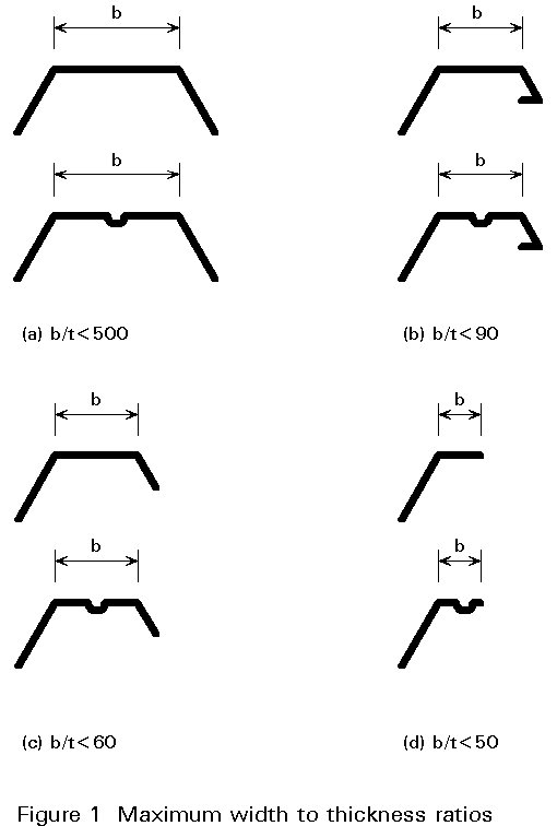
Limits for b/t ratios
The design rules give limits for b/t ratios as shown in Figure 1. These maximum width-to-thickness ratios depend partly on limited experimental evidence, and partly on experience from manufacturing and handling sections. Wide and flexible elements are prone to mechanical damage; the effective area is small compared to the total area, and buckles at service loads may be visible; some sections with high b/t ratios may, however, perform well and "design by testing" is, therefore, also recommended.
Formulae for effective width
Elements of a section can be doubly supported (e.g. webs or flanges with adequate edge stiffeners); singly supported, e.g. flanges of U- or L-profiles, or elastically supported, e.g. flanges with insufficiently stiff edge stiffeners. For doubly and singly supported elements, the critical buckling stress fcr (bifurcation stress) under uniformly distributed normal stresses or even stress gradients provides the basis for the effective-width concept of the Winter formula (see Lecture 9.1) with the buckling factor ks referred to the actual system and loading case. Appropriate ks values can be obtained in the design codes.
Doubly supported elements
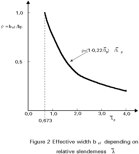
The effective width ratio of a compression element is as follows:
r = bef / bp (1)
with bef = effective width and bp = total width,
At the ultimate limit state (see Lecture 9.1):
r = (1 - 0,22/![]() p)/
p)/![]() p
£
1
(2)
p
£
1
(2)
and ![]() p = 1,052(bp/t) Ö(s1/Eks) £ 0,673
(3)
p = 1,052(bp/t) Ö(s1/Eks) £ 0,673
(3)
For ![]() p = 0,673 this formula gives r = 1,0, i.e. the element is fully
effective. Corresponding values of r
and
p = 0,673 this formula gives r = 1,0, i.e. the element is fully
effective. Corresponding values of r
and ![]() p
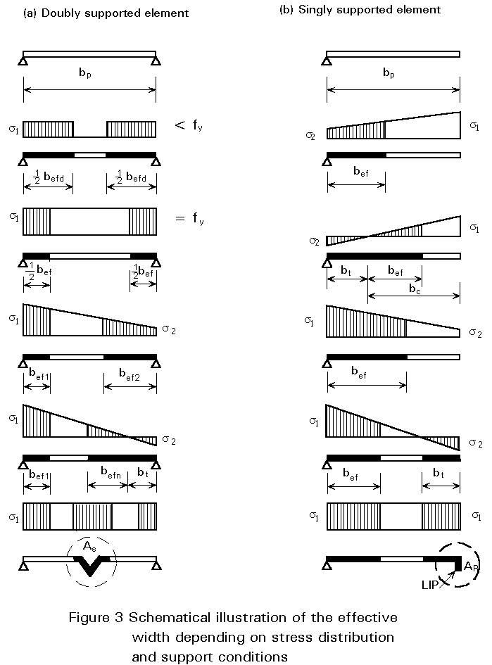
are illustrated in Figure 2. The effective width is allocated to
both sides of the plate element for constant stress in the
subcritical state. If non-uniform stress distributions are
present, the total effective width is divided into two parts (bef1
and bef2), depending on the stress ratio y = s2/s1, with s1
= fy as the maximum compressive stress and s2 ³
0. In the area of tensile stresses (bt), the section
is always taken as fully effective (see Figure 3).
p
are illustrated in Figure 2. The effective width is allocated to
both sides of the plate element for constant stress in the
subcritical state. If non-uniform stress distributions are
present, the total effective width is divided into two parts (bef1
and bef2), depending on the stress ratio y = s2/s1, with s1
= fy as the maximum compressive stress and s2 ³
0. In the area of tensile stresses (bt), the section
is always taken as fully effective (see Figure 3).
At the ultimate limit state, the compressive stress s1 corresponds to the yield strength fy (s1 = fy); at serviceability limit state s1 may be taken as equal to fy/1.5.
Singly supported elements
For singly supported elements similar solutions can be derived, using appropriate ks values. In this case, however, when calculating the effective width it is important to note whether the maximum compressive stress is located at the supported or unsupported side of the element (Figure 3).
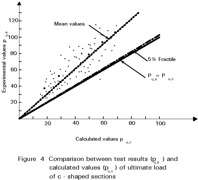
Validity of the effective width concept
Comparisons between test results and analytically derived buckling loads of C-shaped sections (Figure 4) and other profiles with different element boundary conditions, have confirmed the practical validity of the design model. One advantage of the effective width concept is that it allows relatively simple methods to be used; it also permits the effect of the section geometry on load bearing resistance to be visualised. This effect can be seen from the values of effective widths referred to different stress distributions and support conditions shown in Figure 3. A practical consequence is that unsupported parts of elements subjected to compressive stresses are ineffective and should be avoided. Their effectiveness can be easily increased by reinforcement of the section by edge stiffeners (lips, bends, folds) and/or intermediate stiffeners. This effect is also qualitatively illustrated in Figure 3.
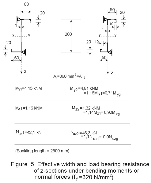
It can also be seen from Figure 5, which shows the load-bearing resistance of Z-shaped profiles with different types of end stiffeners under bending moments and normal forces respectively, that even small changes of geometrical properties provide increased load-bearing resistances.
Treatment of stiffeners and lips
An effective measure to increase the load-bearing resistance and stiffness of thin-walled sections, is to reduce the flat width of elements of a section in compression by intermediate stiffeners, and to provide singly-supported flat parts with edge stiffeners (bends or folds). If the stiffness of the stiffener itself is sufficiently high, it can act as a rigid support to adjacent flat parts (see also Fig. 14 of Lecture 9.1). This means that no collapse of the stiffener, caused either by yielding or instability of the stiffener itself, is allowed to occur before the supported element is itself at the ultimate state. Normally it is impossible to provide such an amount of stiffness which means that an interaction between the adjacent element and the stiffener has to be considered.
Since the analytical solution to the problem is very difficult and impractictical, an approximate solution has been developed based on the component's physical behaviour. In Figure 6, three different buckling modes are illustrated, which represent the following:
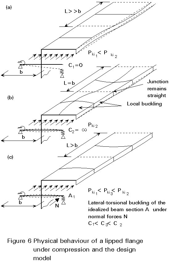
This behaviour can be simulated by the "beam on elastic foundation" model in which the beam is represented by parts of the lip and the strip, and the elastic foundation by a spring stiffness which represents the restraint to the strip.
Simplified design of stiffeners
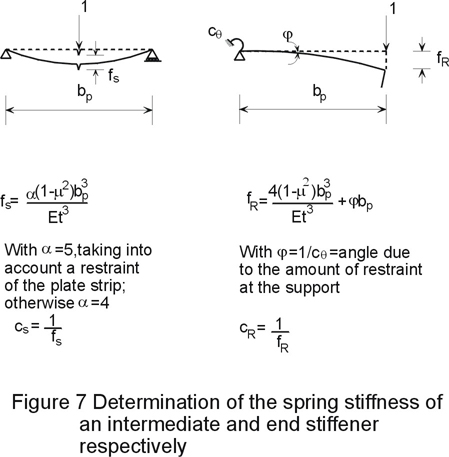
Based on the physical behaviour described above, the design model requires the estimation of an effective section, and the spring stiffness of the "foundation". Then, the ideal critical buckling load of the section (Ncr) and the reduced ultimate load (Nu), depending on the relative slenderness, can be determined. The spring stiffness of an intermediate stiffener mainly depends on the bp/t ratio of the compressed element and that of an edge stiffener (e.g lips or foldings) on the amount of restraint at the opposite side of the strip. The determination of the spring stiffness is demonstrated in Figure 7.
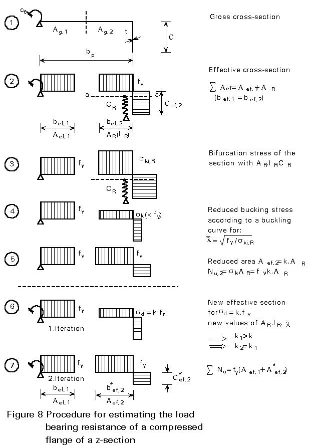
The procedure for the determination of the load-bearing resistance of the compression flange of a Z section is illustrated in Figure 8 where the steps are as follows:
| Step 1 | The spring stiffness CR = 1/fR is determined, taking into account the rotational stiffness at the support due to the adjacent web. |
| Step 2 | Determination of the
effective width of the plate element and the lip
respectively, assuming a hinged support at the
junction Þ SAef = bef,1.t + AR [= (bef,1 + Cef,1).t]. |
| Step 3 | Having calculated IR,
the moment of inertia of the cross-section with area AR
(referred to the axis a-a of AR), the ideal
buckling stress ski,R
is given by: ski,R = (2/AR) Ö(CR EIR) representing the bifurcation stress of the beam on elastic foundation. |
| Step 4 | Determination of the related
slenderness |
| Step 5 | or, referred to the yield stress, Nu,2 = fy (k .AR) which means that AR has to be reduced to a value of Aef,2 = k .AR (equivalent section). |
If k is substantially less than 1,0, an iterative process with at least two steps (6 and 7) can improve the load-bearing resistance so that at the end of the iteration k » 1,0 and Nu,n = fy.Aef,*2. The total load-bearing resistance is then SNu = fy (Aef,1 + Aef,*2).
The effect of an intermediate stiffener can be determined in a similar way. The validity of this model has been confirmed by tests.
Other considerations
In preparing the design procedure, the enhancement of the yield strength caused by the cold-forming process (see Lecture 9.1), can be taken into account, bearing in mind that roundings of corners (radii) have to be considered in the evaluation of section properties.
The design procedure for axially loaded thin-walled columns mainly follows the procedure for compact sections, that is: choice of the buckling curve (a-c) with reference to the type of the section; calculation of the section properties (Ief,Aef) and the slenderness (l) of the columns; derivation of the related slenderness, f(l, fy); and estimation of the buckling factor a and the design buckling load Nd. For this procedure the following aspects must be considered:
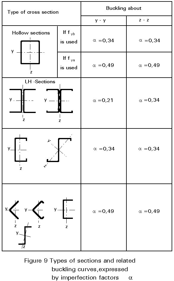
Buckling curves and types of sections
Types of sections and related buckling curves (a-c), represented here by imperfection factors a = 0,21 - 0,34 - 0,49, are shown in Figure 9. The more the section is prone to local buckling or to twisting the more the a-values increase and the buckling reduction factors decrease. This fact underlines the need to consider in the design the actual type of loading the section undergoes.
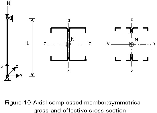
Buckling of symmetrical sections
The effective cross-section is calculated on the assumption of constant compressive stresses, acting on the gross cross-section. For symmetrical sections the neutral axis of the effective section is identical with that of the gross cross- section and the member has to be checked for pure compression forces only.
The procedure is then as follows:
Ag, Aef, Q = Aef/Ag
Ief,ief = Ö(Ief/Aef), l = L/ief referred to the appropriate axis (y,z)
l1 = Ö(E/fy)
l/l1 =

a-value according to Figure 9.
f = 0,5[1 + a(
k = 1/{f + [f2 -
NRd = kAeffy/gM (6)
Buckling of unsymmetrical sections
For unsymmetrical sections (see Figures 11 and 12), the neutral axis of the effective section (if Aef/Ag< 1) shifts with respect to that of the gross cross-section. Since concentric compression is defined as the normal force acting at the centroid of the effective section, this case will be only valid if the load is made concentric by constructional arrangements.
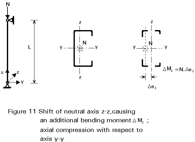
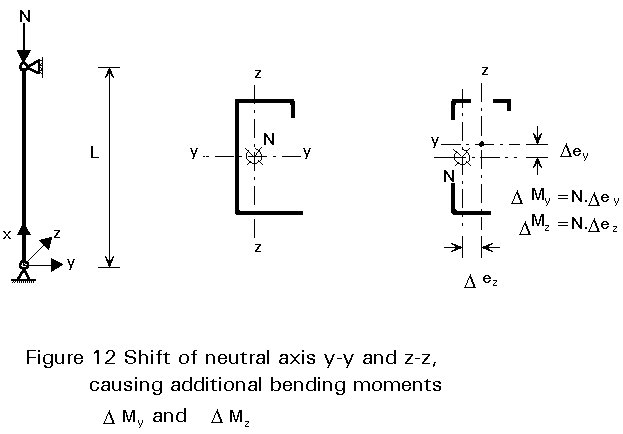
Normally the shift of the neutral axis will produce an additional bending moment, Mb = N.e, which has to be taken into account in the same way as flexural buckling. The additional moment caused by an interaction of normal forces and external bending moments. In general, all members subjected to combined bending and axial compression must satisfy the following conditions:
![]() (7)
(7)
where:
DMy, DMz are the additional bending moments due to the shift of the neutral axis.
My, Mz are the nominal external bending moments according to first order theory.
MRd,y, MRd,z are the design bending moments referred to the effective cross section.
ky, kLT, kz are enhancement factors to cover second order effects.
Equation (7) covers the case of combined bending, and axial compression with lateral-torsion buckling if Md,y is the design bending moment considering lateral- torsional buckling, and if kLT is the appropriate enhancement factor.
[1] European Convention for Constructional Steelwork: "European Recommendation for the Design of Light Gauge Steel Members", Publication 49, ECCS, 1987.
[2] Eurocode 3, Part 1.3: "Cold-Formed Steel Sheeting and Members" CEN (in preparation).