ESDEP WG 8
PLATES AND SHELLS
To introduce basic aspects of the behaviour and design of plate girders. To explain how the typical proportions employed influence the types of behaviour that must be addressed in design, and to identify the various buckling considerations involved, as a preparation for subsequent consideration of the design approaches of Eurocode 3 [1].
None
Lectures 3.2: Erection
Lecture 7.2: Cross-section Classification
Lecture 7.3: Local Buckling
Lecture 8.1: Introduction to Plate Behaviour and Design
Lecture 8.4.2: Plate Girder Behaviour and Design - II
Lecture 8.4.3: Plate Girder Design - Special Topics
Lecture 11.8: Splices in Buildings
Lecture 14.4: Crane Runway Girders
Lecture 15B.3: Plate Girder and Beam Bridges
Modern plate girders are introduced by explaining typical usage, types and the reasons for their inherent slender proportions. Their behaviour is described with particular emphasis on the different forms of buckling that can occur. The general basis of plate girder design is discussed in a simplified way as a prelude to a more detailed presentation in Lectures 8.4.2 and Lecture 8.4.3. Post-buckling and tension field action are introduced and the roles of the main components in a plate girder identified.
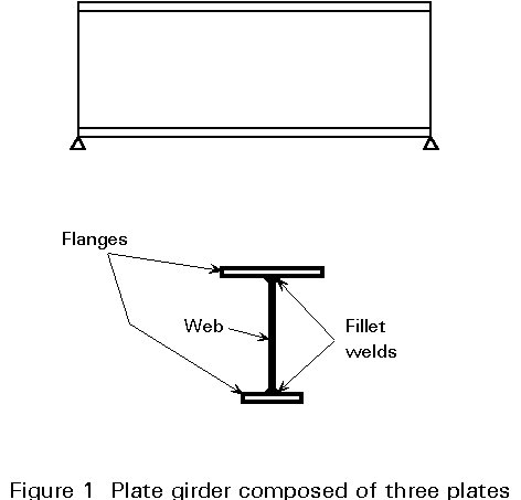
Modern plate girders are normally fabricated by welding together two flanges and a web plate, as shown in Figure 1. Such girders are capable of carrying greater loads over longer spans than is generally possible using standard rolled sections or compound girders. Plate girders are typically used as long-span floor girders in buildings, as bridge girders, and as crane girders in industrial structures.
Plate girders are at their most impressive in modern bridge construction where main spans of well over 200m are feasible, with corresponding cross-section depths, haunched over the supports, in the range of 5-10m. Because plate girders are fabricated separately, each may be designed individually to resist the applied actions using proportions that ensure low self-weight and high load resistance.
For efficient design it is usual to choose a relatively deep girder, thus minimising the required area of flanges for a given applied moment, Msd. This obviously entails a deep web whose area will be minimised by reducing its thickness to the minimum required to carry the applied shear, Vsd. Such a web may be quite slender (i.e. a high d/tw ratio) and may be prone to local buckling (see Lecture 7.3) and shear buckling (see below). Such buckling problems have to be given careful consideration in plate girder design. One way of improving the load carrying resistance of a slender plate is to employ stiffeners (Lecture 8.1); the selection of appropriate forms of stiffening is an important aspect of plate girder design.
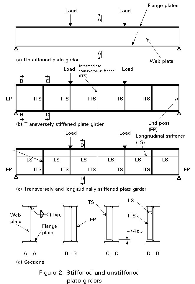
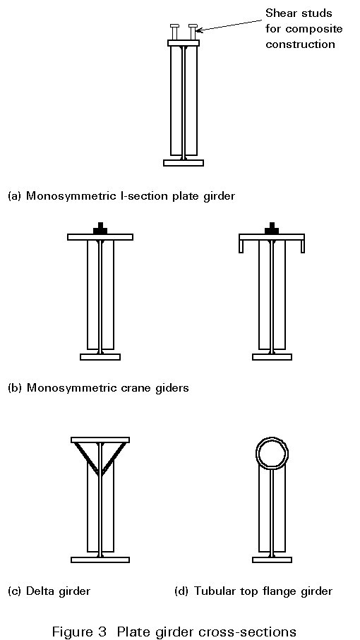
There are several forms of plate girder; Figure 2 illustrates three different types - unstiffened, transversely stiffened, and transversely and longitudinally stiffened. The three girders shown have bisymmetric I-profile cross-sections, although flanges of different size are sometimes used, as already shown in Figure 1. Other types of cross-section (see Figure 3) are monosymmetric I-profiles, which are popular in composite construction with the smaller flange on top (see Lecture 10.2), or as crane girders (see Lecture 14.4) with the larger flange on top. Figure 3 also shows two other (less common) variations - the "delta girder" and the tubular-top-flange girder - both being possible solutions in cases of long laterally-unsupported top compression flanges prone to lateral-torsional buckling (see Lecture 7.9.1 and 7.9.2).
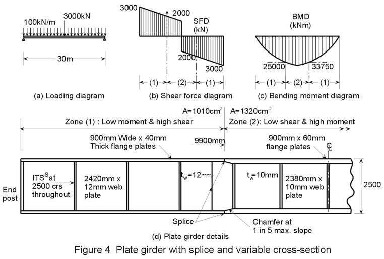
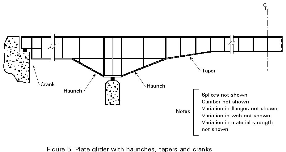
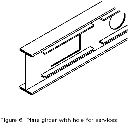
There is also considerable scope for variation of cross-section in the longitudinal direction. A designer may choose to reduce the flange thickness (or breadth) in a zone of low applied moment, especially when a field-splice facilitates the change. Equally, in a zone of high shear, the designer might choose to thicken the web plate (see Figure 4). Alternatively, higher grade Fe E355 steel might be employed for zones of high applied moment and shear, while standard grade Fe E235 would be used elsewhere. So-called "hybrid" girders with different strength material in the flanges and the web offer another possible means of more closely matching resistance to requirements. More unusual variations are adopted in special circumstances, such as bridgework (see Lecture 15B.4) e.g. tapered girders, cranked girders, haunched girders (see Figure 5), and of course, plate girders with web holes to accommodate services, see Figure 6.
Since the designer, in principle, is quite free to choose all the dimensions of a plate girder, some indication of the more usual proportions is now given (see also Figure 7):
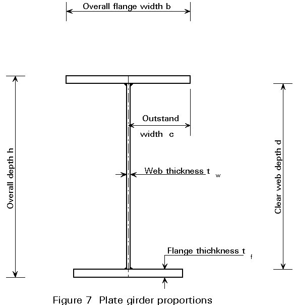
Depth: Overall girder depth, h, will usually be in the range Lo/12 £ h £ Lo/8, where Lo is the length between points of zero moment. However, for plate girder bridges the range will extend to approximately Lo/20.
Flange breadth: The breadth, b, will usually be in the range h/5 £ b £ h/3, b being in multiples of 25mm. 'Wide flats' may be used unless the flange is very wide.
Flange thickness: The flange thickness, tf, will usually at least satisfy the requirements of Eurocode 3 (Table 5.3.1) for Class 3 (semi-compact) sections, i.e. c/tf £ 14e. The thickness will usually be chosen from the standard plate thicknesses.
Web thickness: Web thickness, tw, will determine the exact basis for web design, depending on whether the web is classified with regard to shear buckling as "thick" or "thin" (see later). Thin webs will often require stiffening; this may take the form of transverse stiffeners, longitudinal stiffeners or a combination, see Figure 2. Longitudinally stiffened girders are more likely to be found in large bridge construction where high d/tw ratios are appropriate, e.g. 200 £ d/tw £ 500, due to the need to minimise self-weight.
Clearly, depending on the particular loading pattern, and on depth and breadth restrictions, one can expect wide variations within all the above limits which should be regarded as indicative only.
Under static loading, ultimate limit states such as strength and stability will normally govern most plate girder design, with serviceability limit states such as deflection or vibration being less critical. Some absolute limits on plate slenderness are advisable so as to ensure sufficient robustness during erection. A generally accepted method [2] for designing plate girders (which is permitted by Eurocode 3) subject to a moment Mad and a coincident shear Vad is to proportion the flanges to carry all the moment with the web taking all the shear. This provides a particularly convenient means for obtaining an initial estimate of girder proportions.
Thus, at any particular cross-section along a laterally-restrained plate girder, subject to specific values of bending moment and shear force, the flange and web plates can be sized separately. The required flange plate area may readily be obtained as follows:
Af = M/[(h - tf)fy/gMO] @ M/(hfy/gMO) (1)
(An iteration or two may be required depending on an assumed value of tf and its corresponding fy value from Table 3.1, Eurocode 3). Because the (normally) slender web will prevent the plastic moment of resistance of the cross-section from being attained, the flange b/tf ratio need only comply with the Eurocode 3 (Table 5.3.1) requirements for a Class 3 (semi-compact) flange. The cross-sectional moment of resistance may then be checked using:
Mf.Rd = b tf (h - tf)fy/gMO (2)
Unfortunately, economic sizing of the web plate is not quite as straightforward, although where a thick web (defined later) is acceptable it can be rapidly sized by assuming uniform shear stress ty over its whole area. The web-to-flange fillet welds must be designed to transmit the longitudinal shear at the flange/web interface.
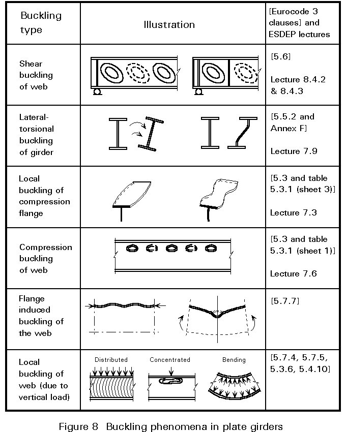
Provided that the individual plate elements in a girder are each kept sufficiently stocky, the design may be based on straightforward yield strength considerations. Economic and practical considerations will, however, dictate that not all of these conditions will always be met. In most cases various forms of buckling must be taken into account. Figure 8 lists the different phenomena.
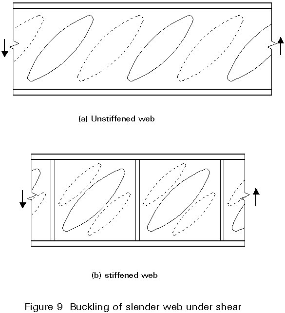
Once the d/tw value for an unstiffened web exceeds a limiting figure (69e in Eurocode 3) the web will buckle in shear before it reaches its full shear capacity Awty. Diagonal buckles, of the type shown in Figure 9(a), resulting from the diagonal compression associated with the web shear will form. Their appearance may be delayed through the use of vertical stiffeners, see Figure 9(b) since the load at which shear buckling is initiated is a function of both d/tw and panel aspect ratio a/d.
This topic is covered in Lecture 7.9.1 and 7.9.2.
Provided that outstand proportions c/tf are suitably restricted, local buckling will have no effect on the girder's load carrying resistance.
Webs for which d/tw £ 124e and which are not subject to any axial load will permit the full elastic moment resistances of the girder to be attained. If this limit of d/tw (or a lower one if axial compression in the girder as a whole is also present) is exceeded, then moment resistance must be reduced accordingly. If it is desired to reach the girder's full plastic moment resistance a stricter limit will be appropriate.
If particularly slender webs are used, the compression flange may not receive enough support to prevent it from buckling vertically rather like an isolated strut buckling about its minor axis. This possibility may be eliminated by placing a suitable limit on d/tw. Transverse stiffeners also assist in resisting this form of buckling.
Vertical loads may cause buckling of the web in the region directly under the load as for a vertical strut. The level of loading that may safely be carried before this happens will depend upon the exact way in which the load is transmitted to the web, the web proportions, and the level of overall bending present.
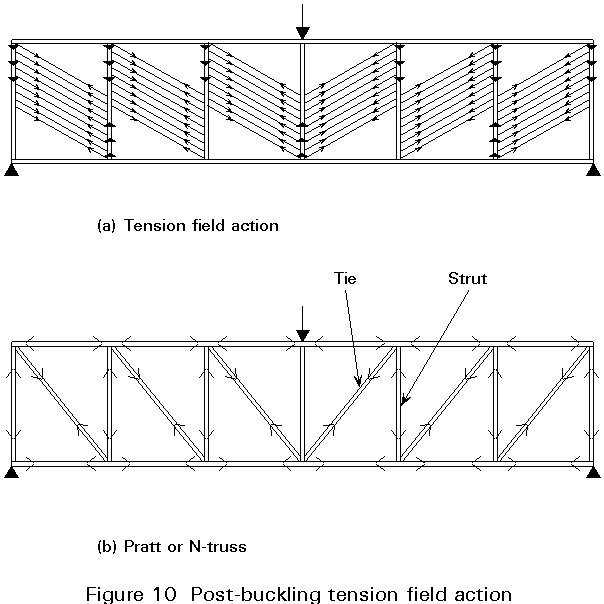
Owing to the post-buckling behaviour (see Lecture 8.3) plates, unlike struts, are often able to support loads considerably in excess of their initial buckling load. In plate girder webs a special form of post-buckling termed "tension field action" is possible. Tension field action involves a change in the way in which the girder resists shear loading from the development of uniform shear in the web at low shear loads, to the equivalent truss action, shown in Figure 10, at much higher loads. In this action the elements equivalent to truss members are: the flanges, which form the chords; the vertical stiffeners which form the struts; and the diagonal tension bands which form the ties. The compressive resistance of the other diagonal of each web panel is virtually eliminated by the shear buckling. The way in which this concept is utilized in design is explained in Lecture 8.4.2.
The principal functions of the main components found in plate girders may be summarised as follows:
|
Flanges |
resist moment |
|
Web |
resists shear |
|
Web/flange welds |
resist longitudinal shear at interface |
|
Vertical stiffeners |
improve shear buckling resistance |
|
Longitudinal stiffeners |
improve shear and/or bending resistance. |
[1] Eurocode 3: "Design of Steel Structures": European Prestandard ENV1993-1-1: Part 1, General rules and rules for buildings, CEN, 1992.
[2] Narayanan, R. (ed)., "Plated Structures; Stability and Strength", Applied Science Publishers, London, 1983.
Chapter 1 covers basic aspects of plate girder behaviour and design.
Chapters 4 and 5 provide more detailed accounts of the main features of plate girder behaviour and design.