ESDEP WG 7
ELEMENTS
To develop an understanding of the phenomenon of lateral-torsional instability; to identify the controlling parameters and to show how theory, experiment and judgement are combined to produce a practical design method. The design procedure given in Eurocode 3 [1] is used as an illustration of such a method.
Lecture 6.1: Concepts of Stable and Unstable Elastic Equilibrium
Lectures 6.6: Buckling of Real Structural Elements
Lectures 7.8: Restrained Beams
Lecture 7.9.2: Unrestrained Beams II
Lectures 7.10: Beam Columns
This lecture begins with a non-mathematical introduction to the phenomenon of lateral torsional buckling. It presents a simple analogy between the behaviour of the compression flange and the flexural buckling of a strut. It summarises the principal factors influencing lateral stability and briefly describes the role of bracing in improving this.
A brief explanation is given of the reasons why the elastic theory, discussed in Lecture 7.9.2, requires modification before being used as a basis for the design rules for unrestrained beams. A summary of the background to Eurocode 3 [1] is also presented.
C coefficient to account for type of loading
d overall depth
EIz flexural rigidity about the minor axis
fd design strength of material
fy material yield strength
iz minor axis radius of gyration
k coefficient to account for conditions of lateral support
L span
Mb.Rd buckling resistance moment
Mcr elastic critical buckling moment
Mpl plastic moment of cross-section
MRd moment resistance of cross-section
tf flange thickness
u lateral deflection
a
LT parameter in design formula, see Equation (2)c
LT reduction factor for lateral-torsional buckling![]() LT
beam slenderness
LT
beam slenderness
l
LT basic slendernessl
1 parameter used to determinef
twistf
LT parameter used to determine cLT, see Equation (2)y
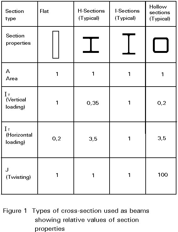
moment ratio, see Equation (5)When designing a steel beam it is usual to think first of the need to provide adequate strength and stiffness against vertical bending. This leads naturally to a cross-sectional shape in which the stiffness in the vertical plane is much greater than that in the horizontal plane. Sections normally used as beams have the majority of their material concentrated in the flanges, which are relatively narrow so as to prevent local buckling. The need to connect beams to adjacent members with ease normally suggests the use of an open section, for which the torsional stiffness will be comparatively low. Figure 1, which compares section properties for four different shapes of equal area, shows that the high vertical bending stiffness of typical beam sections is obtained at the expense of both horizontal bending and torsional stiffness.
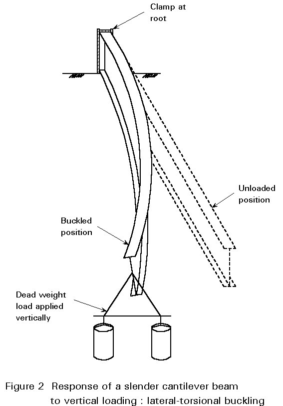
It is known from our understanding of the behaviour of struts that, whenever a slender structural element is loaded in its stiff plane (axially in the case of the strut), there exists a tendency for it to fail by buckling in a more flexible plane (by deflecting sideways in the case of the strut). Figure 2 illustrates the response of a slender cantilever beam to a vertical end load; this phenomenon is termed lateral-torsional buckling. Although it involves both a lateral deflection (u) and twisting about a vertical axis through the web (f), as shown in Figure 3, this type of instability is quite similar to the simpler flexural buckling of an axially loaded strut. Loading the beam in its stiffer plane (the plane of the web) has induced a failure by buckling in a less stiff-direction (by deflecting sideways and twisting).

Of course, many types of construction effectively prevent this form of buckling, thereby enabling the beam to be designed with greater efficiency as fully restrained (see Lecture 7.8.1). In this context it is important to realise that during erection of the structure certain beams may well receive far less lateral support than will be the case when floors, decks, bracings, etc., are present, so that stability checks, at this stage, are also necessary.
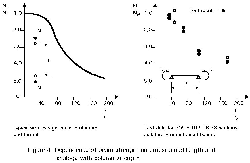
Lateral-torsional instability influences the design of laterally unrestrained beams in much the same way that flexural buckling influences the design of columns. Thus the bending strength will now be a function of the beam's slenderness, as indicated in Figure 4, requiring the use in design of an iterative procedure similar to the use of column curves in strut design. However, because of the type of structural actions involved, the analysis of lateral-torsional buckling is considerably more complex. This is reflected in a design approach which requires a rather greater degree of calculation.
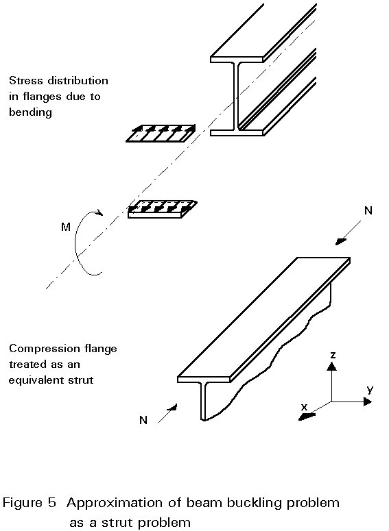
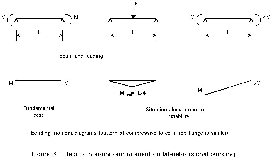
Before considering the analysis of the problem, it is useful to attempt to gain an insight into the physical behaviour by considering a simplified model. Since bending of an I-section beam is resisted principally by the tensile and compressive forces developed in two flanges, as shown in Figure 5, the compression flange may be regarded as a strut. Compression members exhibit a tendency to buckle and in this case the weaker direction would be for the flange to buckle downwards. However, this is prevented by the presence of the web. Therefore the flange is forced to buckle sideways, which will induce some degree of twisting in the section as the web too is required to deform. Whilst this approach neglects the real influence of torsion and the role of the tension flange, it does, nevertheless, approximate the behaviour of very deep girders with very thin webs or of trusses or open web joists. Indeed, early attempts at analysing lateral-torsional buckling started with this approach.
The compression flange/strut analogy, discussed in the previous section, is also helpful in understanding the following:
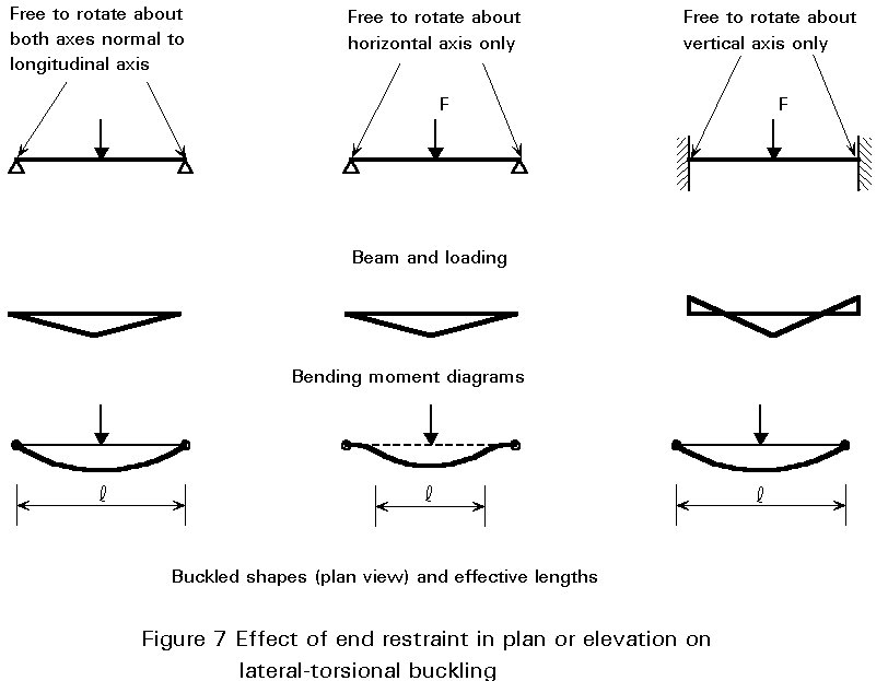
A more rigorous analysis, substantiating the above four points, is presented in Lecture 7.9.2. This lecture also deals with warping of the cross-section and the influence of level of application of load on stability; factors not illustrated by the simplified model presented here.
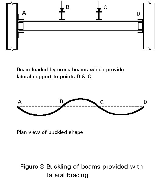
Bracing may be used to improve the strength of a beam that is liable to lateral-torsional instability. Two requirements are necessary:
Providing these two conditions are satisfied, then the full in-plane strength of a beam may be developed through braces at sufficiently close spacing. Figure 8, which illustrates buckled shapes for beams with intermediate braces, shows how this buckling involves the whole beam. In theory, bracing should prevent either lateral or torsional displacement from occurring. In practice, consideration of the buckled shape of the beam cross-section shown in Figure 3 suggests that bracing is potentially most effective when used to resist the largest components of deformation, i.e. a lateral brace attached to the top flange is likely to be more effective than a similar brace attached to the bottom flange.
Direct use of the theory of lateral-torsional instability for design is inappropriate because:
Figure 9 compares a typical set of lateral-torsional buckling test data obtained using actual hot-rolled sections with the theoretical elastic critical moments given by Equation (17) of Lecture 7.9.2.
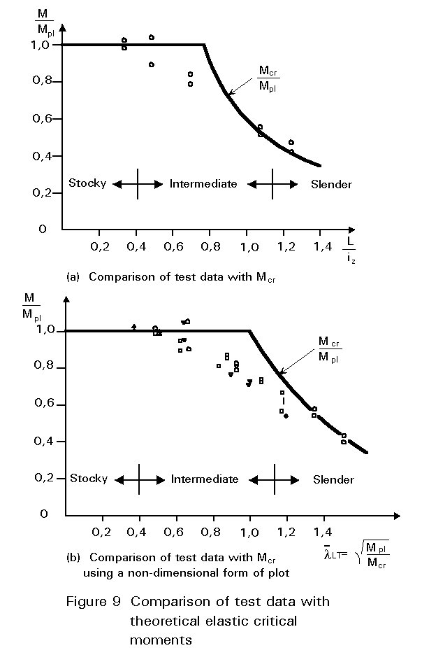
In Figure 9a only one set of data for a narrow flanged beam section is shown. The use of the
![]() LT
non-dimensional format in Figure 9b has the advantage of permitting results from different test series (using different cross-sections and different material strengths) to be compared directly. In both figures three distinct regions of behaviour can be observed:
LT
non-dimensional format in Figure 9b has the advantage of permitting results from different test series (using different cross-sections and different material strengths) to be compared directly. In both figures three distinct regions of behaviour can be observed:
Only in the case of beams in region 1 does lateral stability not influence design; such beams can be designed using the methods of Lecture 7.8.1. For beams in region 2, which covers much of the practical range of beams without lateral restraint, design must be based on considerations of inelastic buckling suitably modified to allow for geometrical imperfections, residual stresses, etc., (see Lecture 6.1). Thus both theory and tests must play a part, with the inherent complexity of the problem being such that the final design rules are likely to involve some degree of empiricism.
Section 7 outlines the provisions of Eurocode 3 [1] with regard to beam design, assuming typical sections as shown in Figure 10a and 10b. It should be noted that sections of the type illustrated in Figure 10b, with one axis of symmetry, e.g.channels, may only be included if the section is bent about the axis of symmetry, i.e. loads are applied through the shear centre parallel to the web of the channel. Singly-symmetrical sections bent in the other plane, e.g. an unequal flanged I-section bent about its major-axis as shown in Figure 10c, may only be treated by an extended version of the theory of Lecture 7.9.2, principally because the section's shear centre no longer lies on the neutral axis.

The buckling resistance moment [1] is given by:
MbRd = cLT MRd (1)
where MRd is the moment resistance of the cross-section
cLT is the reduction factor for lateral-torsional buckling
In determining MRd the section classification should, of course, be noted and the appropriate section modulus used in conjunction with the material design strength fd. The value of cLT depends on the beam's slenderness
![]() LT
and is given by:
LT
and is given by:
cLT = 1/ {fLT
+ [fLT2 - ![]() LT2]1/2}
(2)
LT2]1/2}
(2)
where fLT = 0,5 [1 + aLT(![]() LT
- 0,20) +
LT
- 0,20) + ![]() LT2]
LT2]
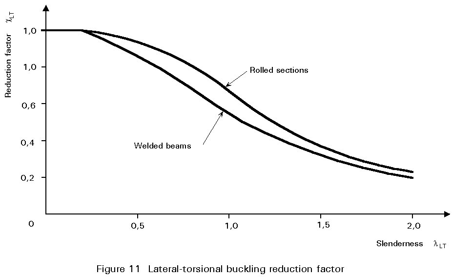
and aLT = 0,21 for rolled sections
aLT = 0,49 for welded beams
Figure 11 illustrates the relationship between cLT and
![]() LT, showing how it follows the pattern of behaviour exhibited by the test data of Figure 9. When
LT, showing how it follows the pattern of behaviour exhibited by the test data of Figure 9. When
![]() LT
£ 0,4, the value of cLT is sufficiently close to unity that design may be based on the full resistance moment MRd.
LT
£ 0,4, the value of cLT is sufficiently close to unity that design may be based on the full resistance moment MRd.
The slenderness ![]() LT, which is a measure of the extent to which lateral-torsional buckling reduces a beam's load carrying resistance, is a function of MRd and Mcr. Mcr is the elastic critical buckling moment, a quantity similar in concept to the Euler load for a strut since it is derived from a theory (see Lecture 7.9.2) that assumes "perfect" behaviour, i.e. an initially straight member, elastic response, no misalignment of the loading, etc..
LT, which is a measure of the extent to which lateral-torsional buckling reduces a beam's load carrying resistance, is a function of MRd and Mcr. Mcr is the elastic critical buckling moment, a quantity similar in concept to the Euler load for a strut since it is derived from a theory (see Lecture 7.9.2) that assumes "perfect" behaviour, i.e. an initially straight member, elastic response, no misalignment of the loading, etc..
Thus ![]() LT
is taken as:
LT
is taken as:
![]() LT
=
LT
= ![]() (3)
(3)
For calculation purposes Equation (3) may be rewritten as:
![]() LT
= [lLT / l1]
(4)
LT
= [lLT / l1]
(4)
where l1 = p[E/fy]1/2
= ![]()
and lLT = 
This expression represents a conservative approximation for any uniform plain I or H shape with equal flanges - see Annex F2 of EC3.
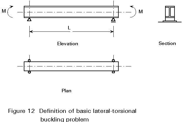
The above expression for lLT is valid for loading giving uniform moment over a span whose ends are prevented from deflecting laterally and from twisting about a vertical axis passing through the web. This is the basic case for lateral stability (Figure 12) for which a full theoretical treatment is provided in Lecture 7.9.2. Variations in the conditions of loading and/or lateral support may be allowed for by introducing modifying factors into the expressions for lLT or Mcr.
For example, if there is a moment gradient between points of lateral restraint, lLT is calculated as follows:
lLT =  (5)
(5)
where C1 = 1,75 - 1,05 y + 0,3 y2 £ 2,35
and y is the end moment ratio defined in Figure 13.
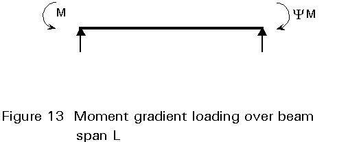
Taking as an example the end span of a continuous beam for which y = 0 gives C1=1,75 and thus lLT will be reduced to 0,76 (= 1/Ö 1,75) of the value for uniform moment, leading to an increase in cLT and thus in MbRd.
Variations in the conditions of lateral restraint may be treated by introducing k-coefficients to modify the geometrical length L into kL when determining Mcr. For conditions with more restraint, values of k < 1,0 are appropriate, leading to an increase in Mcr and thus, via a reduction in
![]() LT, to increases in cLT and MbRd.
LT, to increases in cLT and MbRd.
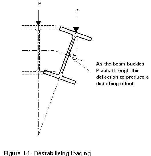
Similarly additional C-coefficients may be used directly in the determination of Mcr to provide modified values of
![]() LT
appropriate for a wide range of load types. In particular, this method should be used to calculate the reduced Mcr appropriate for destabilising loads. These are loads that act above the level of the beam's shear centre and are free to move sideways with the beam as it buckles, as shown in Figure 14.
LT
appropriate for a wide range of load types. In particular, this method should be used to calculate the reduced Mcr appropriate for destabilising loads. These are loads that act above the level of the beam's shear centre and are free to move sideways with the beam as it buckles, as shown in Figure 14.
For cross-sections of the type illustrated in Figure 9c, for which the shear centre and centroid do not lie on the same horizontal axis, evaluation of Mcr becomes more complex and is covered by Annex F of Eurocode 3 [1].
[1] Eurocode 3: "Design of Steel Structures": ENV 1993-1-1: Part 1.1: General rules and rules for buildings, CEN, 1992.
Chapters 1 - 3 deal with various aspects of behaviour and design of laterally unrestrained beams.
Chapter 3 deals with laterally unrestrained beams.
Basic derivations for the elastic critical moment for a variety of beam problems are provided in Chapter 6.
Chapter 4 presents the basic theory of lateral buckling of beams.
Chapter 2 deals with the fundamentals of elastic behaviour, whilst Chapter 3 covers elastic and inelastic behaviour and design of laterally unrestrained beams.
Laterally unrestrained beams are dealt with in Chapter 6.