ESDEP WG 7
ELEMENTS
To introduce the concept of effective length and to describe its application in the design of practical columns.
Lecture 6.3: Elastic Instability Modes
Lectures 7.5: Columns
Lecture 7.6: Built-up Columns
Lecture 7.11: Frames
Lectures 7.12: Trusses and Lattice Girders
Worked Example 7.7: Effective Lengths
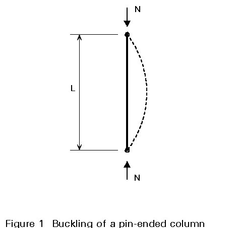
For pin-ended columns the buckling length equals the actual length; such columns are, however, relatively rare in practice. Predicting strength under other than pin-ended conditions can be achieved by using the notion of effective length (LE).
LE is the length of a similar pin-ended column (of the same section) which has the same buckling load as the column being considered. Approximate values for effective length, which can be used in design, are given for a wide range of end-restraint conditions.
For the determination of the elastic Euler critical buckling load
![]() (1)
(1)
it is assumed (Lectures 6.1. and 7.5.1) that both ends of the column are pinned (Figure 1); practical end connections on real columns, however, will often not behave in this manner and this will, therefore, significantly affect the buckling load. Two aspects of the end condition must be considered:
The usual design approach consists of reducing the practical case under consideration to an equivalent pin-ended case by means of an effective length factor K.
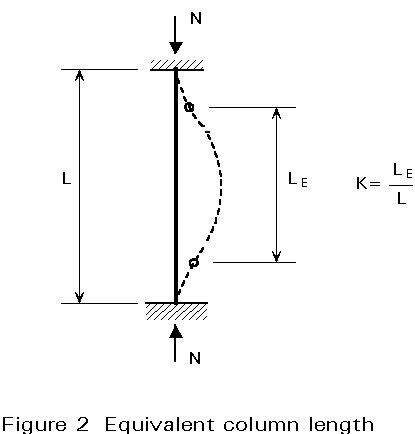
The effective length, LE, of a member hinged at its ends is the distance between the axes of the hinges. For general end restraints, the effective length LE, is the length of an end-hinged member which has the same load bearing resistance as the member under consideration.
The application of the above definition is not easy in practice. Numerical studies have shown that the notion of effective column length can be derived from elastic stability theory. In this case the effective length factor, K, is the ratio of the length (LE) of the equivalent column to the actual length (L); and the length of the equivalent column is the distance between two consecutive points of contraflexure (points of zero moment) in the actual column (Figure 2).
For the pin-ended column (fundamental case of buckling of a prismatic bar, see Figure 1) the effective length factor is equal to 1, and the distance between the points of zero moment is equal to the actual column length.
More generally, let us consider, for example, the columns of the frame illustrated in Figure 3a; if it is assumed that the flexural rigidity of the beam is much higher than that of the columns, no rotation of the upper ends of the columns occurs when the frame moves laterally. This situation is shown in Figure 3b.
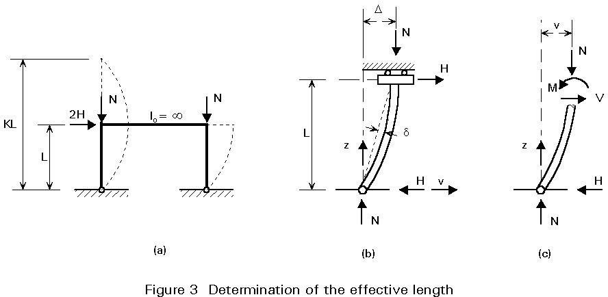
The bending moment at a point along the column is given by
M = Nv + Hz (Figure 3c).
The differential equation becomes:
![]() (2)
(2)
Using the notation K2 = N/EI:
![]() (2b)
(2b)
The solution of Equation (2b) is given by:
![]() (3)
(3)
To find the constants A and B, the boundary conditions are used:
for z = 0, v = 0 and for z = L, ![]() = 0, therefore A = 0 and
= 0, therefore A = 0 and
B K cos K L = 0 (4)
From (4), it follows that either B or cos K L = 0.
If B = 0, v = -Hz/N and d2v/dz2 = 0; in this case, the bending moment M should be zero at any point along the column.
The other possibility is that cos KL = 0 and this condition requires that K = np/2L where n = 1,3,5, .... (5)
To obtain the smallest value of N for which Equation (5) is satisfied, using n=1 gives KL = p/2 from which K = p/2L and K2 = N/EI,
Ncr = K2 EI = p2 EI/4L2 = p2 EI/(2L)2 (6)
The comparison of Equations (6) and (1) shows that the effective length factor K is equal to 2 and therefore, that the effective length of the column is twice the actual length. In other words, the critical load for the column of length L, shown in Figure 3, is the same as the critical load of a pin-ended column of length 2L. The situation is shown geometrically in Figure 3a.
The use of an effective column length is basically a device to relate the behaviour of columns with any form of support to the behaviour of the basic pin-ended case. The design procedure for columns with particular end conditions is the same as for pin-ended columns (see Lecture 7.5.1) but in establishing the design strength from the column design curve, the slenderness (LE/ry) would be used instead of L/ry.
Table 1 gives theoretical K-values for idealized conditions in which the rotational and/or translational restraints at the ends of the column are either fully realized or non-existent. Each of these values is obtained as for the previous example.
Table 1 also recommends K-values which are equal or slightly higher than the equivalent theoretical values derived from elastic stability theory. When higher values are specified it is usually in recognition of the practical difficulties of providing complete restraint against rotation or translation.
The comparison of cases (b) and (e) in Table 1, shows the influence of the translational restraints on the buckling load. Case (e) represents the situation of the column of Figure 3a, with lateral displacement, while in case (b) no translation is permitted; the buckling load is multiplied by a factor 8 ((2,0/0,7)2) when translation is prevented. For this reason, it is absolutely necessary that the designer knows the difference between sway and non-sway frames.
According to Eurocode 3 [1], a frame may be classified as non-sway if its response to in-plane horizontal loads is sufficiently stiff for it to be acceptably accurate to neglect any additional internal forces or moments arising from horizontal displacement of its nodes. Any other frame shall be treated as a sway frame and the effects of the horizontal displacements of its nodes taken into account in its design.
More details concerning the distinction between sway and non-sway frames are given in the Lectures 14.
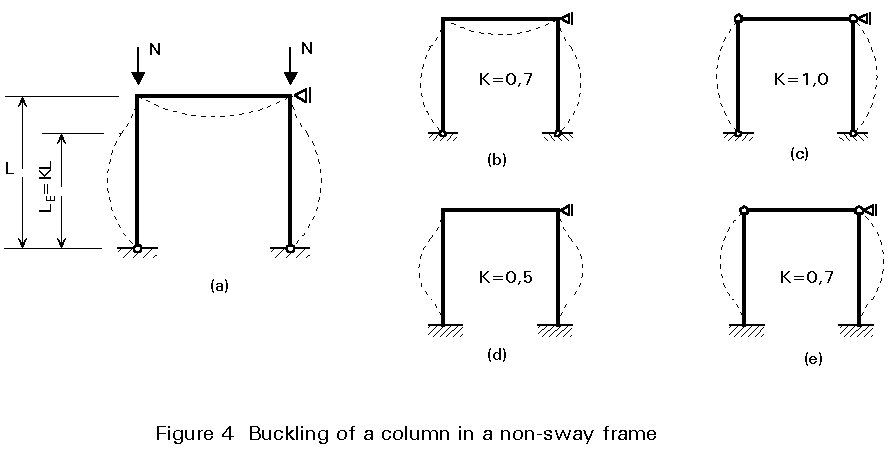
A column in a non-sway frame would have no sideways movement at the top relative to the bottom. The buckling of a non-sway frame would result in a buckled column shape having at least one point of contraflexure between the ends of the member, such as cases (a), (b), and (c) of Table 1 (see Figure 4). The effective length factor K is always less than or equal to 1 (0,5 £ K £ 1).
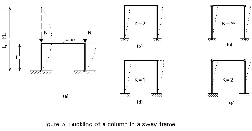
In a sway frame, the top of the column moves relative to the bottom. Cases (d), (e) and (f) of Table 1 are sidesways buckling cases which are illustrated in Figure 5. The effective length factor K is always greater than or equal to 1 and is unlimited (1 £ K £ ¥).
The above considerations concerning single storey frames can be generalized, so as to extend to frames of more than one storey.
The fully rigid end-restraints (shown in Figures 4b, 4d, 5b and 5d) can rarely be achieved in practice and partial end-restraints are much more common.
In the case of partial end-restraint the effective length factor K can be determined either by a generalized second order rotation method or by using stability functions [2].
The solution to the problem is expressed in the form:
K = f(ht,hb) (7)
where ht and hb, are elastic restraint coefficients at the top and bottom of the column considered.
Simplified approaches are available for evaluating the effective length factor K, [3-7].
Using Donnell's approximate formula [3] (see Figure 6)
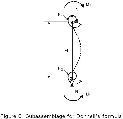
K = 1/Ön (8)
where n = ![]() (9)
(9)
and ![]() (10)
(10)
In the case of a compressed bar of a truss
![]() (11)
(11)
where Ri = Sj 3EIj/lj (12)
characterizes the restraint of the adjacent bars, "j".
Wood [4] and Johnston [5] have given other simplified approaches differing only in their presentation.
In Eurocode 3 [1], the approach suggested by Wood has been adopted and two cases are considered: non-sway and sway frames.
In some cases, a compressed bar can be supported elastically at several intermediate points along the length. Figure 7 shows, for example, the compressed chord of a truss girder; the intermediate supports of the chord are represented by the framed cross girder.
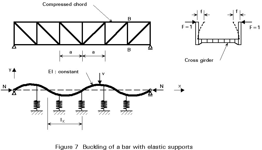
In such a case the effective length is greater than the distance "a" between the cross girders [8] and is given by:
![]() (13)
(13)
where f = 1/Kr, the displacement of a spring (intermediate support) due to a unit force.
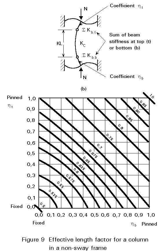
Wood [4], considers a sub-element of a non-sway frame as illustrated in Figure 8b (part AB of the frame represented in Figure 8a.).
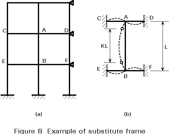
The two elastic restraint coefficients ht and hb (which are closely analogous to the cross-distribution coefficients at the upper and lower ends of the column) are calculated using the following formulae:
ht = KC/(KC + SKb,t) (14)
hb = KC/(KC + SKb,b) (15)
where KC is the column stiffness I/L
SKb is the sum of effective beam stiffness at a joint and the suffices b and t indicate the bottom or top end of the column.
Where the beams are not subject to axial forces, their effective stiffnesses can be determined by reference to Table 2, provided that they remain elastic under the design moments.
Where, for the same load case, the design moment in any of the beams exceeds the elastic moment, the beam should be assumed to be pinned at the point or points concerned.
Where a beam has semi-rigid connections its effective stiffness should be reduced accordingly.
Where the beams are subject to axial forces, their effective stiffnesses should be adjusted accordingly; stability functions can be used in this case. As a simple alternative, the increased stiffness due to axial tension can be neglected and the effects of axial compression can be allowed for by using the conservative approximations given in Table 3.
Considering the sub-element illustrated in Figure 8b, and the distribution coefficients given above yields results that can be graphically illustrated [4] by the curves of Figure 9. These can also be represented by the following expression:
![]() (16)
(16)
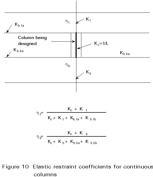
The model can be adapted for the design of continuous columns, by assuming that each length of column is loaded to the same value of the ratio (N/Ncr). In the general case, where (N/Ncr) varies, this leads to a conservative value of K for the most critical length of column.
For each length of a continuous column this assumption can be introduced using the model shown in Figure 10 and obtaining the distribution coefficients ht and hb as follows:
![]() (17)
(17)
![]() (18)
(18)
In unbraced frames (and some braced frames) sway is permitted; the effective length factor, K, is therefore greater than unity and can tend towards infinity if the horizontal beams are very flexible.
K can be calculated using the same approach as that adopted for frames in which sway is prevented; it should, however, be pointed out that the results for sway frames must be considered as even more approximate than those given for non-sway frames.
Wood's method can be considered as acceptable when sway is permitted only if the frames are regular, i.e. heights, moments of inertia and axial forces in the columns do not differ considerably.
The effective length factor of a column in a sway frame may be obtained from Figure 11 or Equation (19):
 (19)
(19)
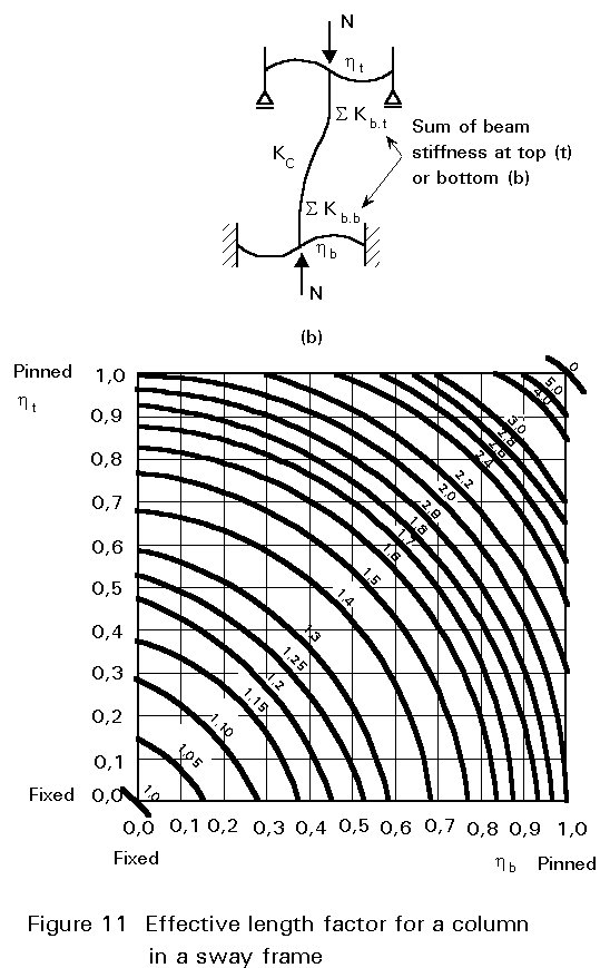
The elastic restraint coefficients ht and hb are calculated as for the case of non-sway frames.
Introducing the effective length concept in the elastic design of sway columns requires that second order or load destabilizing effects (due to the displacement of the top of the columns) are approximately taken into account by an effective length factor K, greater than 1. The advantage of this approach is its simplicity but it should be recognised that it is limited and may, in some cases, be inaccurate.
A design considering the whole structure, based on approximate methods for elastic critical load analysis, is recognized as more reliable. These methods consider the effects of horizontal sway forces on the structure which subject the column to bending moments as well as axial loads. More information on this topic is given in Lecture 7.11.
[1] Eurocode 3: "Design of Steel Structures": ENV 1993-1-1: Part 1.1: General rules ad rules for buildings, CEN, 1992.
[2] Livelsey, R.K. and Chandler, P.B., "Stability Functions for Structural Frameworks", Manchester University Press, 1956.
[3] Massonnet, Ch., "Flambement des Constructions Formées de Barres Droites". Note technique B10.52, CRIF, Bruxelles, 1955.
[4] Wood, R.H., "Effective Lengths of Columns in Multistorey Buildings". The Structural Engineer, vol. 52, 1974 (pp. 235-244; 295-302; 341-346).
[5] Johnston, G., "Design Criteria for Metal Compression Members". John Wiley and Sons, Inc., New York, 1960.
[6] Djalaly, H., "Longueur de Flambement des Eléments de Structures". Construction métallique, no. 4, 1975.
[7] Kamal Hassan., "Zur Bestimmung der Knicklänge of Rahmenstreben", IVBH Abhandlungen 28-I-1968.
[8] SIA 161, Constructions Metalliques 1979.
Table 1 Effective length factor for centrally loaded columns with various end conditions
|
With lateral restraint (a) (b) (c) |
Without lateral restraint (a) (b) (c) |
|||||
|
Ideal buckling conditions |
|
See Fig T1-2 | ||||
|
Theoretical K-values |
1,0 |
0,7 | 0,5 |
2,0 |
2,0 | 1,0 |
|
Recommended K-values when ideal conditions are approximated |
1,0 |
0,8 | 0,65 |
2,0 |
2,0 | 1,2 |
Table 2 Effective stiffness of a beam
|
Conditions of rotational restraint at far end of beam |
Effective beam stiffness (provided beam remains elastic) |
|
Fixed at far end |
1,0 I/L |
|
Pinned at far end |
0,75 I/L |
|
Rotation as at near end (double curvature) |
1,5 I/L |
|
Rotation equal and opposite to that at near end (single curvature) |
0,5 I/L |
|
General case. Rotation QA at near end and QB at far end |
(1 + 0,5 QB/QA) I/L |
Table 3 Approximate formulae for reduced stiffness due to axial compression
|
Far end condition |
Effective beam stiffness |
|
Fixed |
1,0 I/L (1 - 0,4 N/Ncr) |
|
Pinned |
0,75 I/L (1 - 1,0 N/Ncr) |
|
Double curvature |
1,5 I/L (1 - 0,2 N/Ncr) |
|
Single curvature |
0,5 I/L (1 - 1,0 N/Ncr) |
|
Where Ncr = p 2 EI/L2 |
|

