ESDEP WG 18
STAINLESS STEEL
To provide information on the processes used in the fabrication of stainless steel structures.
Lecture 18.1: Introduction to Stainless Steel
Lecture 18.2: Structural Behaviour and Design
Lecture 18.3: Corrosion of Stainless Steel
The lecture discusses the importance of the maintenance of the corrosion resistance of the stainless steel during the operations of forming, machining and joining. The main characteristics of machining and shaping techniques used to fabricate stainless steel structures are reviewed.
Stainless steel is not a difficult material to work with. However, in some respects it is different from carbon steel and should be treated accordingly. Many fabrication and joining processes are similar to those used for carbon steel, but the different characteristics of stainless steel require special attention in a number of areas. It is important that effective communication is established between the designer and fabricator early in the project to ensure that appropriate fabrication practices can and will be adopted.
An overriding objective is to maintain the steel's corrosion resistance. It is essential that precautions are taken, at all stages of storing, handling, forming and welding, to minimise mechanical or other damage of the surface, i.e. the oxide layer. Although essential, the precautions are simple and, in general, are a matter of good engineering practice.
It is important to preserve the good surface appearance of stainless steel throughout fabrication. Not only are surface blemishes unsightly, but they are usually unacceptable and prove time-consuming and expensive to correct. Whereas surface blemishes will normally be hidden by paint in carbon steel structures, this will only be rarely so in stainless steel structures.
The structural form may be dictated by the availability of materials. It should be recognised that the available range of hot rolled stainless sections is more limited than for carbon steel. This limitation results in a greater use of cold-formed and welded members than is normally encountered. Also, because of brake press length capabilities, only relatively short lengths are possible. As a result there is an increased use of splices. In detailing joints, consideration should be given to clearances for bolts near bend radii and to potential fit up problems arising from weld distortion.
Generally, greater care is required in storing and handling stainless steel than carbon steel to avoid damaging the surface finish (especially bright annealed or polished finishes) and to avoid contamination by carbon steel and iron. Storage and handling procedures should be agreed between the relevant parties to the contract in advance of any fabrication and in sufficient detail to accommodate any special requirements. The procedures should cover, for instance, the following items:
Stainless steel is a expensive material compared to some other metals and particular care is needed therefore in marking out plates and sheets to avoid wastage in cutting. More wastage may result if the material has a polishing grain (or a unidirectional pattern) which has to be maintained in the fabrication. The marks made by some pens/crayons are difficult to remove, or cause staining, if used directly on the surface (rather than on any protective film). The marking pens/crayons to be used should be checked that they are satisfactory in this respect.
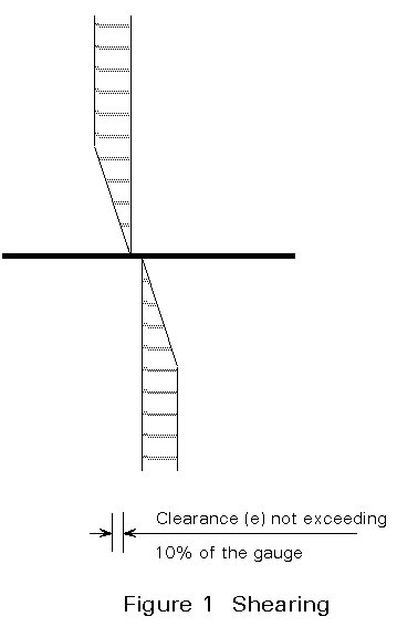
Stainless steel may be cut using normal methods, e.g. shearing (Figure 1) and sawing, but power requirements are greater than for similar thicknesses of carbon steel due to work hardening. Greater power is needed for the austenitic grades in particular. If possible cutting (and machining in general) should be carried out when the metal is in the annealed (softened) state to limit work hardening and tool wear.
For cutting straight lines, shearing by guillotine is widely used. By using open ended guillotines, a continuous cut greater in length than the shear blades can be achieved although at the risk of introducing small steps in the cut edge.
Plasma arc techniques are also used and are particularly useful for cutting thick plates and profiles and where the cut edges are to be machined, e.g. for weld preparation. Oxyacetylene cutting is not satisfactory for cutting stainless steel unless a powder fluxing technique is used.
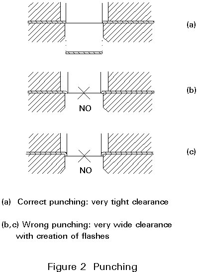
Holes may be drilled or punched. During drilling, positive cutting must be maintained to avoid work hardening. For this purpose sharp bits with correct angles of rake and correct cutting speeds are required. The use of a round tipped centre punch is not recommended as this work hardens the surface. A centre drill should be used or, if a centre punch has to be used, it should be of the triangular pointed type. Punched holes can be made in austenitic stainless steel up to about 20 mm in thickness. The minimum diameter of hole that can be punched out is 2 mm greater than the sheet thickness. The minimum distance between punched holes should be half the hole diameter. Punched holes should be avoided in corrosive environments due to the presence of the work hardened edge (Figure 2), unless they are reamed after punching.
Particular account must be taken of the poor conductivity typical of all stainless steels and especially of the austenitic grades. Otherwise local overheating may occur with consequent localized warping and work hardening which may cause stress corrosion.
Moreover, on stainless steels which are neither low-carbon nor stabilized, chromium carbide precipitations may occur with the danger of subsequent intergranular corrosion should the pieces come into contact with agents which could induce it. (In practice intergranular corrosion is only a problem in acidic environments where the stainless steel has been welded.)
The wheels consist of abrasives with an aluminium oxide and silicon carbide base and have medium-hard and hard bonds. It is important that abrasives do not contain any iron components.
Care should be taken not to use wheels for grinding stainless steel which have already been used for grinding carbon-steel. Otherwise the surface of the stainless steel element will be contaminated and discoloration may result.
Stainless steel is readily shaped by commonly used cold-forming techniques such as bending, spinning, pressing and deep drawing. For structural applications press brake bending is the most relevant technique although, for high volume thin gauge products, roll forming may be more economic.
For these processes to be successful it is recommended that the stainless steel be in the softened state.
Furthermore it should be remembered that, given the same gauge being worked, greater force is needed than for forming carbon-steel and lower forming speeds, especially for the austenitic grades, are needed.
In the case of extreme forming particular care must be paid to lubrication.
This method is used for obtaining sections of various shapes. Presses of the type used for carbon-steel are employed.
The best bending conditions are those when the bending axis of the sheet or strip is perpendicular to the rolling direction to avoid cracking. However it is always possible to make bends with the axis parallel to the rolling direction, especially with austenitic grades.
The edges of the ends of the strip and sheet must be flash-free, otherwise cracks may occur, especially if the bending radius is small in comparison to the gauge. The springback is greater than that of carbon steel. Thus suitable over-bend angles must be planned to obtain the required bend angles in the finished piece.
Elastomer matrices are used successfully for folding stainless steel strip and sheet. They have the advantage over steel ones in that they give maximum protection to the surface finish and provide a guarantee against contamination.
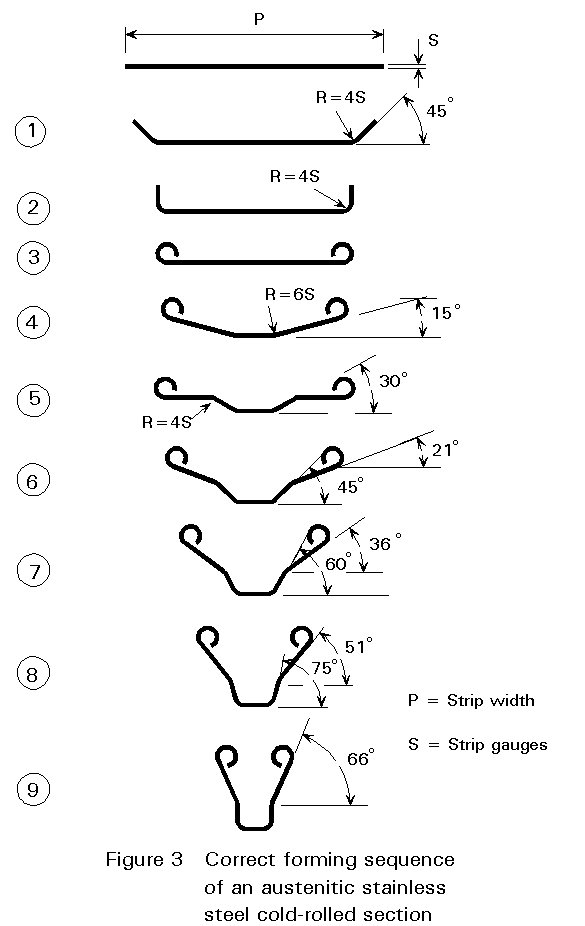
The forming of the strip is done by a continuous succession of bends around axes parallel to the rolling direction (the worst condition). Thus it is necessary to grade the angles and the radii of curvature suitably depending on the gauge of the strip. It is also advisable to keep the strip in tension during forming by increasing the diameters of the rollers by about 1% at each roll stand from the entry ones of the exit ones.
Figure 3 shows a correct forming sequence for stainless steel strip. The values of the angles and the radiuses of curvature, phase by phase, for an austenitic grade are given.
For sheet and strip, bending is by three-roll forming, a method similar to that used for carbon steel, but it should be remembered that the springback is greater, especially for the austenitic grades.
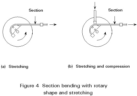
For cold-rolled or press bent sections, the bend is usually made by stretching and possibly also using compression (Figure 4) to avoid puckering. Puckering can occur in stainless steels, which are generally used with thinner gauges than carbon steel. This technique also allows the springback effects to be reduced.
For tubes, which are also generally used with thinner gauges than the carbon-steel ones, particular care is required. The most appropriate technique is to use rotating shaper machines, preferably fitted with a chuck, and possibly articulated for extreme bends.
In the most common case of welded pipes it is advisable, especially for the ferritic grades, to locate the weld in correspondence with the neutral fibre. The springback is particularly great for the austenitic grades.
The blank has an area equal to the sum of the base and side areas of the finished elements, possibly with the addition of a peripheral section to take account of the size of the flange required to regulate the material flow (Figure 5). The thickness of the blank depends on that of the sides of the finished item, bearing in mind that the final thickness can be reduced by as much as 20-30%.

The shape of the blank is circular when the finished element has cross-sections compatible with that shape. A polygonal shape is used when the cross-sections are non-circular.
When very deep drawing is required, a suitable heat treatment to soften the material must be provided to facilitate drawing after the material has reached its limit.
The junction radiuses and the clearances between punch and die are particularly important (Figure 6).
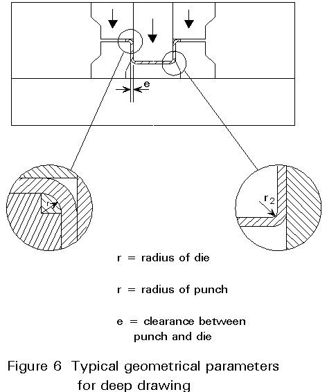
Particular care must be taken over the choice of materials and the finish of the dies, and also in the lubrication to avoid seizing.
It is necessary to be well aware of the differences in the physical properties of stainless steels and in comparison to carbon steel.
Reference should be made to the specialized literature to determine the correct operating parameters. In particular, in environments where intergranular corrosion could occur, it is prudent to select low carbon or stabilized stainless steels when welding thicker material, the limiting thickness being dependent on welding process and actual environment. All the welding techniques can be used with the austenitic grades, but there are particular instructions for welding ferritic and martensitic grades.
Stainless steels can also be welded together with carbon steel to give hybrid structures. Appropriate techniques should be employed, including strongly alloyed filler metal and electrodes to compensate for the dilution of the welding pod due to the presence of carbon steel. When welding is complete, all the carbon steel, including the weld bead, must be carefully protected with a suitable paint coating. Such hybrid structures must be carefully designed to avoid the dangers of bi-metallic corrosion.
These techniques involve the fusion of the edges of the parts to be joined, together with that of the filler metal.
Normally all austenitic grades can be fusion welded. For other types of stainless steel, it is necessary to examine each situation and select the most suitable system.
The techniques most commonly used in practice are:
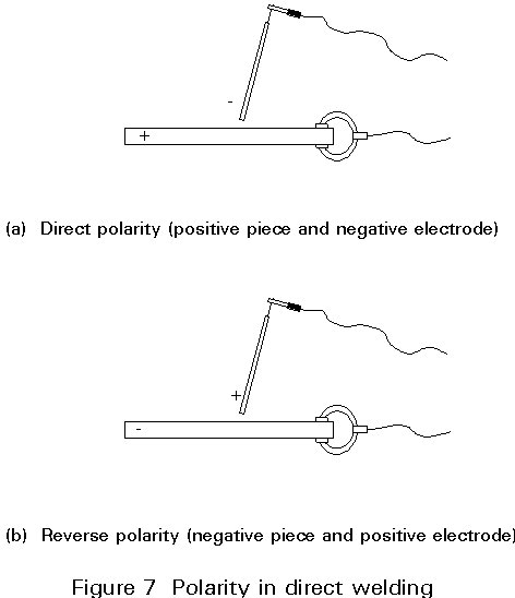
Direct current welding tools should be used for preference and reverse polarity employed to ensure better penetration (Figure 7).
This technique can be used on gauges of not less than 1 to 1,5 mm and does not need special preparation of the edges up to a gauge of about 4mm. For joints with larger gauges special edge preparation is needed using an appropriate caulking tool.
The pieces to be welded must be firmly held together, especially the austenitic grades, since these materials have a high thermal expansion coefficient.
This technique is a much used welding system for stainless steels, particularly for the austenitic grades.
The electrode consists of a non-consumable bar of tungsten-thorium alloy and the arc is protected by a jet of inert gas (argon with the possible addition of hydrogen). It is used with direct polarity (Figure 7).
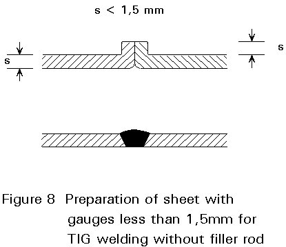
It is not necessary to use filler rod for gauges up to 1,5 mm with suitable preparation (Figure 8), while for larger gauges (up to 5 - 6 mm, which is the practical limit for this technique) filler metal must be used. The edges must in all cases be well mated and well fixed together.
To achieve a proper weld, especially in the case of the thicker gauges, the inert gas protection must also be applied to the reverse of the weld.
This technique differs from the previous one in that the electrode consists of a consumable stainless steel wire wound on a reel. The starting gas is composed of suitable argon-based mixtures depending on the transfer system for the filler metal during welding.
Basically, the welding systems used are: short arc (and its derivation, pulsed arc) for gauges less than 2 - 3,5 mm and spray arc for thicker gauges up to about 8 mm. For greater thicknesses the method is of less interest.
This is a welding technique which always operates in the presence of inert gas and which, with the "key-hole" method, allows the weld to be made in a single pass without any special preparation of the pieces which must be simply mated and held together. The feed uses direct polarity.
Welding speed is considerably greater than for the other systems mentioned.
The micro-plasma system can be used for gauges between 0,02 mm and 1,5 mm inclusive.
Fusion of a small part of the materials to be joined is achieved with this technique. Filler metal is not required and the joint at the junction point is achieved by the Joule effect.
The technique can be used for all types of stainless steels since these steels have significant electrical resistivity.
This method can be used for gauges between about 0,4 and 3 mm inclusive.
It should be remembered that it is always necessary with this type of welding to exert more force on the electrodes than that used, given equal gauges, for carbon steel.
The other parameters do not differ much from those used for carbon steel in the case of ferritic and martensitic grades. Appropriate parameters are needed for the austenitic grades (lower current and shorter welding time).
This method allows continuous welding of gauges between about 0,5 to 4 mm.
In this case too the pressure on the electrodes must be greater than that used for carbon steel, given equal gauges. Suitable welding parameters must be chosen for the austenitic grades, while the parameters do not differ much from the carbon steel ones for the ferritic and martensitic grades.
Joints made with this system are tight for both water and gas.
When two stainless steel items are joined it is absolutely necessary to use elements of stainless steel or of other materials with an equivalent resistance to corrosion.
If bolts, rivets and screws, of carbon steel or other non-noble materials were to be used they would corrode rapidly due to electrolytic corrosion. The stainless steel structure would act as a large cathode and the joining element, in this case, would act as a small anode.
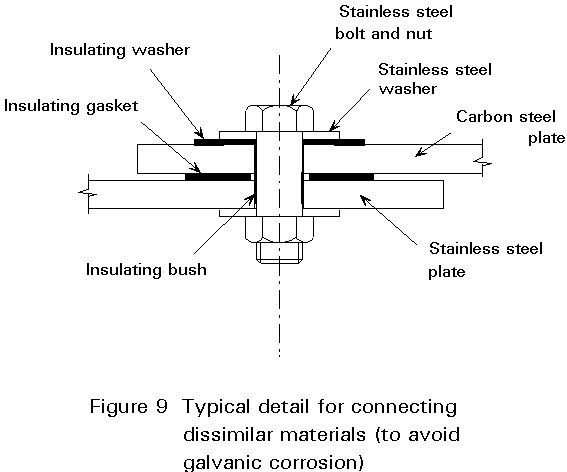
When stainless steel items are joined to carbon steel structural elements the carbon steel element must be well protected by suitable painting. Stainless steel rivets, screws and bolts must be used and the carbon steel element must be suitably insulated from the stainless steel element (Figure 9).
Stainless steel rivets, screws and bolts (which act as small cathodes) can be used for structures made of other less noble materials (which act as large anodes) without any particular precautions.
It is recommended that bolting material should be in the cold-worked condition, property class 70 minimum. Bolting materials should not be used in the softened condition because of the propensity for galling. This propensity is reduced by:
Lock welding of the nut to the bolt should never be allowed as materials are formulated for strength and not fusion welding.
Stainless steels can be bonded to each other or to other materials to make structural joints. Many types of adhesives can be used (cyanoacrilate resin, epoxy resin, phenolic resin, polyurethane resin, etc.) depending on the characteristics required from the joint.
It is important to stress that, when using this type of joining technique, the joint must be properly designed and executed.
It is not possible to use this method for joints designed to be made with welds.
Non-destructive inspection methods to detect surface and/or internal faults in stainless steel items and manufactured articles are related to some properties of the various types of the stainless steels.
The following methods can be used on all types of stainless steels:
The following methods can only be used on ferritic and martensitic steels:
The surface finish of stainless steel is an important design criterion and should be clearly specified according to architectural or functional requirements. The finer the finish, the greater the cost. Precautions taken during early handling and welding help substantially to reduce finishing costs. Initial planning is important in reducing costs. For example, if the tube to tube weld in a handrail or balustrade is hidden inside an upright, there will be a reduced finishing cost and a significant improvement in the final appearance of the handrail.
The surface of steel should be restored to its corrosion resisting condition by removing all scale and contamination. Pickling in an acid bath will loosen any scale, enabling it to be brushed off with a plastic or stainless steel bristle brush, and it will also dissolve any embedded iron or carbon steel particles.
Abrasive treatments, such as grinding, finishing, polishing and buffing, produce unidirectional finishes. Thus the blending of welds may not be easy on plates/sheets with normal rolled surfaces. A degree of experimentation may be required to determine detailed procedures for obtaining a suitable finish.
Electrolytic polishing removes a thin surface layer. A range of finishes from dull to a bright lustre can be produced, depending largely on the initial surface of the material.
There are other finishing processes (electroplating, tumbling, etching, colouring, and surface blackening). These processes are rarely used for structural stainless steel and so are not mentioned further here.
It is worth noting again that the surface should be free of contaminants in the assembled structure. Particular consideration should be given to the possibility of contamination arising from work on adjacent carbon steelwork, especially from grinding dust. The stainless steel should be protected by removable plastic film, or final cleaning after completion of the structure should be specified.