ESDEP WG 18
STAINLESS STEEL
To discuss the mechanical behaviour of stainless steel and to examine how this leads to differences in structural behaviour of members composed of stainless steel and carbon steel. Other factors that a designer should consider are also covered.
Lecture 18.1: Introduction to Stainless Steel
Lecture 18.3: Corrosion of Stainless Steel
Lecture 18.4: Fabrication
The designer of stainless steel structures has to consider carefully the selection of material grade. The austenitic grades are appropriate for the great majority of applications. Greater use will be made of cold formed open sections and welded components as hot rolled sections may either be unavailable or uneconomic. The non-linear and strain hardening characteristics of stainless steel necessitates the use of different design curves to those applicable for carbon steel and introduces difficulties for plastic global analysis. Compared to carbon steel structures, serviceability criteria are more important with stainless steel structures.
Stainless steel has been used for over 50 years in construction, mainly in fixings, fasteners and cladding applications. Certain industries, such as the nuclear, petrochemical, pharmaceutical, paper-making and mining industries, impose greater demands on materials than those met in common construction. These demands relate to durability and corrosion resistance. In many instances stainless steel can provide a maintenance-free, cost effective, structural solution. Stainless steel can also provide exceptional ductility, fire resistance and non-magnetic properties, all of which may be required in particular circumstances. In addition to these advantages, stainless steel can provide extremely cleanable and hygienic surfaces. It finds therefore wide application in food processing and preparation, and in medical fields.
Stainless steel is therefore used as a constructional material, and often has to withstand significant loads. It is important to realise that the verification of a stainless steel structure requires similar checks to those used for carbon steel structures. However, because of differences in material characteristics between stainless steel and carbon steel, the design curves and formulations applicable to each material also differ.
It is worth remarking at this stage that a greater amount of design effort can normally be justified for stainless steel because of the relatively higher initial cost of the raw material. This applies to the design of components (i.e. members and connections) and, in the case of structures where aesthetics are important, to the initial planning to reduce expensive finishing operations. For example, in the case of the handrail of a balustrade, hiding the handrail splice joints in the upright members considerably reduces any weld blending operations and leads to a much improved end product.
For the designer who is not familiar with stainless steel[1], there are a number of potential difficulties and pitfalls:
i. There are apparently a bewildering number of stainless steel grades to choose from, and possible further confusion arises from the existence of the number of different designation systems in use today. Lecture 18.1 discusses these designation systems and their variants.
ii. There is a common misconception that stainless steel does not suffer corrosion whereas in certain adverse circumstances it may, in fact, suffer surface staining or even more severe attack. This behaviour emphasises the need to select an appropriate grade of stainless steel.
iii. The range of hot produced stainless steel sections is smaller than that for carbon steel, particularly for less commonly specified grades of stainless steel.
iv. As compared to carbon steel, the efforts of the designer in stainless steel have a greater bearing on the success of fabrication operations, and indeed on whether the structure can be built at all. In particular, this consideration applies to members and structures fabricated by welding.
Of the various groups of stainless steel (see Lecture 18.1) it is the austenitic steels which are the most useful for construction. These stainless steels offer the best combination of corrosion resistance, strength, formability, weldability and economy. In certain circumstances the more highly alloyed duplex steels with their superior strengths and corrosion resistance, or the cheaper ferritic steels but of lower corrosion resistance, may be considered.
To select the most appropriate grade of stainless steel the following must be taken into account:
a. the environment of the application and the degree of corrosion resistance required.
b. the fabrication route.
c. surface finish.
d. strength.
e. product availability.
f. economy.
The designer should be aware that not all structural forms are available in all the various grades of stainless steel. This, in particular, applies to sections where it may be impossible to obtain, say, an I-beam in the less commonly used grades. A brief overview of product availability is given below.
Sheets and Plates
These products are widely available in all grades. However there may be some restrictions for particular high strength grades (such as the duplex grades) in very thin gauges due to the difficulty in cold rolling. Sheet and plate products are the starting point for cold formed or welded shapes.
Tubular Products
A wide variety of seamless and welded tubular products is available in commonly specified grades, e.g. 304, 316, 304L and 316L, and in grades which are often used in process pipework, e.g. certain duplex grades.
Bar Products
These products are widely available.
Hot Extruded Products
Hot extruded products may be suitable for large volume runs of complex cross-section, e.g. glazing bars. Further advice should be sought.
Hot Rolled Products
They exist for the more common grades up to a maximum dimension (depth or width) of about 300mm. In some European countries these products are difficult to obtain or are very expensive compared to fabricated (cold formed or welded) equivalents.
Cold Drawn Products
Only very small sizes are presently available, e.g. angles up to 50mm x 50mm x 3mm, and then only in a small range of grades. Such products have high yield strength properties due to the work hardening imparted during the drawing process.
Cold Rolled/Cold Bent Products
These products are used commonly as structural sections and are supplied in all grades. They are generally cheaper than hot produced sections, cold drawn sections or sections fabricated by welding. However, because stainless steel work hardens considerably, the forming loads are greater (by about 50% in the case of the austenitic steels) than geometrically equivalent carbon steel sections. As a result shorter lengths of stainless steel sections can be cold bent. Allied with this is the length capacity of brake presses. Thus, in all but small structures, there is a tendency to have more splice joints in stainless steel than in carbon steel. The designer should liaise with the fabricator to establish potential length limitations at an early stage in the design process.
The stress-strain behaviour of stainless steels differs from that of carbon steel in a number of respects:
a. Non-linearity
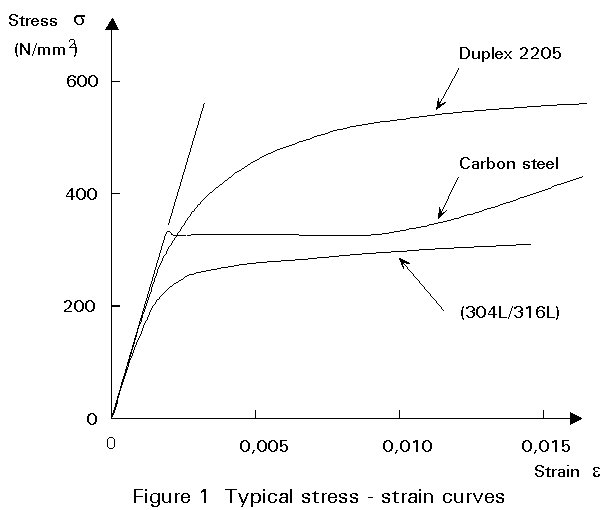
The most important difference between stainless and carbon steels is in the shape of the stress-strain curve. Whereas carbon steel typically exhibits linear elastic behaviour up to the yield stress and a plateau before strain hardening is encountered, stainless steel has a more rounded response with no well-defined yield stress (see Figure 1). Therefore, stainless steel "yield" strengths are generally quoted in terms of a proof strength defined for a particular offset permanent strain (conventionally the 0,2% strain) as indicated in Figure 1.
b. Non-symmetry of tensile and compressive behaviour
Stainless steel may exhibit quite different stress-strain behaviour in tension and compression. For the annealed condition, the stress-strain curves tend to be (although not always) more non-linear in tension than in compression. This behaviour does not necessarily occur for materials which have been cold worked.
c. Anisotropy
Except perhaps for the annealed condition, stainless steel displays differences in stress-strain behaviour for coupons aligned parallel and transversely to the rolling direction, i.e. it is anisotropic. For austenitic grades, the strength of a tensile transverse coupon tends to be lower than that of a longitudinal coupon. This observation is recognised by national and international codes in that transverse coupons are normally specified for proving tests.
Thus, when non-linearity, non-symmetry and anisotropy are considered, a full description of material behaviour is characterised by four stress-strain curves.
a. Strain-rate
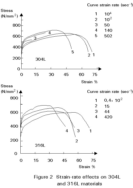
Stainless steels tend to be more sensitive to a change in testing rate than are carbon steels. Figure 2 shows some results for 304L and 316L materials for fast strain rates. Generally, an increase in strain rate leads to higher ultimate strengths and lower ductility.
b. Room-temperature creep
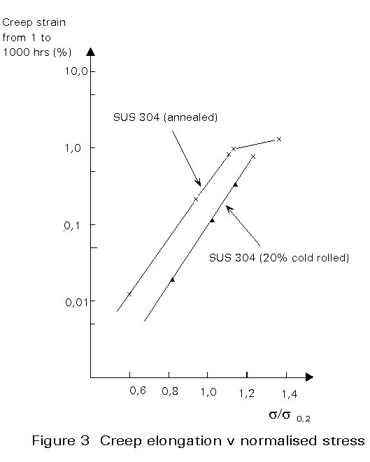
In common with some other metal alloys, although not with carbon steel, stainless steel is subject to creep-like deformation at room temperature [2]. Figure 3 shows some results for 304 material. This facet of behaviour may only become a design consideration where high levels of loading (i.e. near the design limit) are applied for long periods (measured in months and years). Creep may be manifested by increased beam deflection. If long-term deflection is an issue, it is tentatively recommended to restrict the serviceability stresses arising from long term loading to 0,6s0,2 where s0,2 is the actual 0,2% proof stress of the material. It should be noted that austenitic materials strengthened by the addition of nitrogen are more susceptible to room temperature creep when loaded to the same proportion of their yield strength.
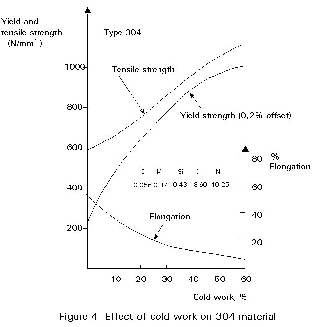
Austenitic stainless steels, in particular, develop high mechanical strengths when cold worked. This behaviour is due in part to a partial transformation of austenite to martensite. The degree of strength enhancement is affected by chemical composition. Austenite stabilising elements such as nickel, manganese, carbon and nitrogen tend to lower the rate of strength enhancement.
Figure 4 shows the effect of cold work on the 0,2% proof stress, the ultimate tensile strength and elongation at failure for a specific cast of 304. Similar relationships apply to other austenitic materials. To maintain a useful ductility of 15%, the amount of cold work should be restricted to 30% for the austenitic grades.
Considerable localised cold working may arise during fabrication such as from the cold forming of corners in sections. Work has been underway to derive formulae for estimating the strength enhancement but it has not yet advanced sufficiently to produce a design proposal.
In general anisotropy and non-symmetry increases with cold work.
It is important to remember that welding or certain heat treatments anneal, or partially so, the cold worked material with a consequent loss of the enhanced strength.
The austenitic stainless steels retain outstanding toughness over a wide range of temperatures; indeed, they are used for the storage of cryogenic liquids.
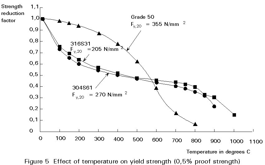
Stainless steels perform better than carbon steel under fire conditions. Figure 5 compares the yield (or 0,5% proof) strength, normalised with respect to room temperature values, of two austenitic stainless steel grades and a carbon steel as a function of temperature. Some grades of stainless steel have been formulated specifically for prolonged exposure at elevated temperature and are used, for instance, in chimney linings.
Density
Most stainless steels have a specific mass laying in the range of 7800 to 8000kg/m3.
Thermal Expansion
Ferritic stainless steels have a coefficient of thermal expansion approximately equal to that of carbon steel. However the austenitic stainless steels have somewhat greater values, up to about 50% more than that of carbon steel. The effects of differential thermal expansion/contraction should be considered in design.
Thermal Conductivity
Stainless steel has a coefficient of thermal conductivity approximately one third that of carbon steel.
Note that this low conductivity leads to steeper thermal gradients and in conjunction with greater thermal expansion causes greater welding residual stresses and distortion (see Section 4.3).
Magnetic Properties
The austenitic stainless steels have low magnetic permeability. Heavy cold working, particularly of lean alloyed austenitic steel, can increase magnetic permeability; subsequent annealing restores the non-magnetic properties. It is recommended to obtain specialist advice for non-magnetic applications.
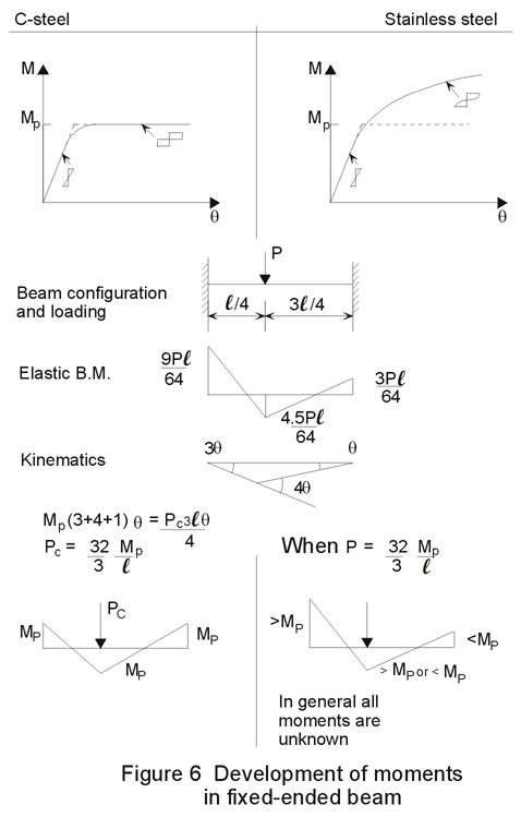
Elastic global analysis is recommended for establishing forces and moments in members. Although in principle plastic global analysis could be used, there are presently certain difficulties to be addressed in design. These difficulties are associated with the strain hardening properties of stainless steel and in particular the moment-rotation characteristics of a stainless steel plastic hinge which likewise displays hardening behaviour. In the formation of a plastic mechanism, plastic hinges are required to undergo various degrees of rotation. Thus the moments at the hinges are above the nominal plastic moment (plastic modulus times the 0,2% proof stress) by varying amounts depending on the degrees of rotation. Therefore the calculation of the distribution of moments around a frame would involve kinematic considerations.
Figure 6 shows the simple example of a fixed ended beam carrying a point load at quarter span. The moments in the stainless steel beam are somewhat indeterminate and depend on the moment-rotation characteristic. Connections would have to resist any additional moment.
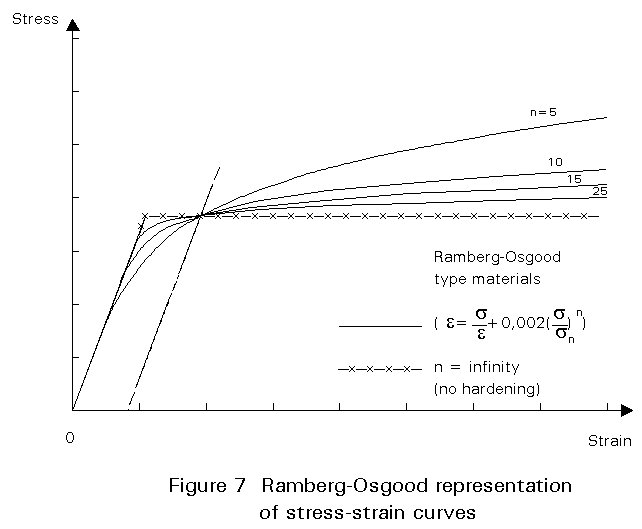
In describing the effect of material non-linearity on the buckling strength of members it is helpful to consider idealised stress-strain curves. One useful idealisation is that proposed by Ramberg and Osgood.
e = s/E + 0,002[s/fy]n (1)
where:
e
is the strains is the stress
fy is the yield (0,2% proof) strength
E is the Young's modulus
n is an index characterising the degree of non-linearity. A low n value gives a very rounded curve whereas high values give curves approaching the bilinear elastic-perfectly plastic relationship of carbon steel, see Figure 7.
In general terms, the effect of non-linearity (as measured by the index n) on member buckling depends on member slenderness as described below. Figure 8 shows the effects graphically and is derived mathematically later.
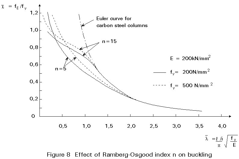
There are three regions of member slenderness:
i. At high slendernesses, i.e. when the buckling strength is low, stresses in the stainless steel member are sufficiently small so that they fall in the linear part of the stress-strain curve. In this range, little difference would be expected between the strengths of stainless and carbon steel members assuming similar levels of geometric and residual stress imperfections. The limiting slenderness beyond which similar behaviour can be expected depends on the proportional limit and hence the n factor in the Ramberg-Osgood representation of the stress-strain curve. This dependence can be see in Figure 8.
ii. At low slenderness, i.e. when members attain or exceed their plastic resistance, the benefits of strain hardening become apparent. For very low slenderness, materials with higher hardening rates, i.e. materials of low n factors, give superior member strengths than materials having high n factors and in particular carbons steels. This effect too can be seen in Figure 8.
iii. At intermediate slendernesses, i.e. when the average stress in the column lies between the limit of proportionality and the 0,2% proof strength, stainless steel is "softer" than carbon steel. This leads to reduced strengths of stainless steel members compared to similar carbon steel members.
In considering instability caused by member buckling, reference is made to the tangent modulus approach. This approach is adopted by the American code for cold-formed stainless steel [3]. The approach is based on replacing Young's modulus E (in carbon steel buckling provisions) by the tangent modulus Et corresponding to the buckling stress in the stainless steel member. Since Et varies with stress and the buckling stress is a function of Et the approach generally requires iterations to find the buckling stress.
An effective design line may be derived by the tangent modulus approach, the necessary iterations having already been carried out for the designer. The derivation can be best demonstrated by way of an example.
Suppose it is required to find the stainless steel curve corresponding to the Euler buckling stress fE for carbon steel columns. For carbon steel (and any linear elastic material):
fE = p2E/(l/i)2
Defining non-dimensional parameters:
cc = fE/fy and ![]() c
= (l/ip)Ö(fy/E)
c
= (l/ip)Ö(fy/E)
in which the subscript c refers to carbon steel, the Euler curve becomes:
cc = 1/![]() c2
c2
For stainless steel, E is replaced by the tangent modulus Et:
fE = p2 Et/(l/i)2
cs = 1/![]() c2
= (1/
c2
= (1/![]() 2)(Et/E)
2)(Et/E)
Using the Ramberg-Osgood relationship for describing the stress-strain curve (Equation (1)) the tangent modulus can be derived as
Et = 
and therefore
![]() =
= 
But, at buckling (f/fy) = cs and so
cs = (1/![]() c2)[1
+ 0,002(nE/fy) csn-1]-1
c2)[1
+ 0,002(nE/fy) csn-1]-1
In general, for any given function cs = f (![]() c), an iterative approach is required to solve the equation obtained at this stage since cs appears on both sides. In the present case the original carbon steel function is simple enough to allow direct solution since, on rearrangement:
c), an iterative approach is required to solve the equation obtained at this stage since cs appears on both sides. In the present case the original carbon steel function is simple enough to allow direct solution since, on rearrangement:
![]() c
c
Note that a family of curves relating
![]() c and cs can be generated for each value of n depending on the ratio of E/fy. Some example curves are compared with the original Euler curve (for carbon steel) in
Figure 8. All the designer has to do now is to calculate
c and cs can be generated for each value of n depending on the ratio of E/fy. Some example curves are compared with the original Euler curve (for carbon steel) in
Figure 8. All the designer has to do now is to calculate
![]() using the initial (Young's) modulus value and then find c directly using the appropriate curve.
using the initial (Young's) modulus value and then find c directly using the appropriate curve.
As can be seen the curves with the lower n value, which implies a lower limit of proportionality, diverge from the carbon steel curve at lower stresses than do the curves associated with the higher n value. However, at stresses above 0,9 fy, the curves with low n value lie above those of high n; this follows from the fact that the tangent modulus of the low n material is greater than that of the high n material in this stress range. It may be noted that a carbon steel stress/strain curve may be closely approximated by very high n values (say >30), in which case the Euler curve is transformed into a horizontal plateau at yield.
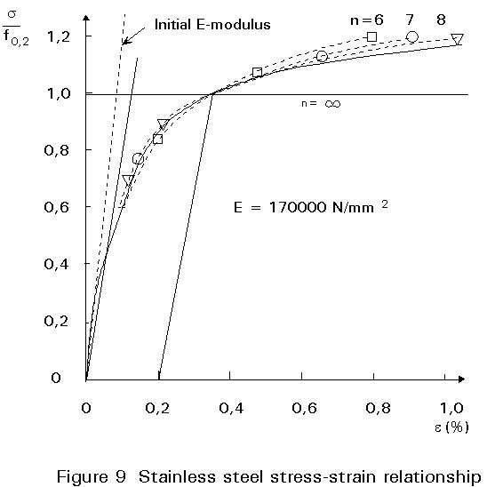
The n value should be estimated as 6 for the austenitic stainless steel in the longitudinal direction. In the transverse direction the higher n values are observed.
The E values given in material standards are usually related to the initial elastic modulus, see Figure 9. For engineering purposes the lower values are used in some standards.
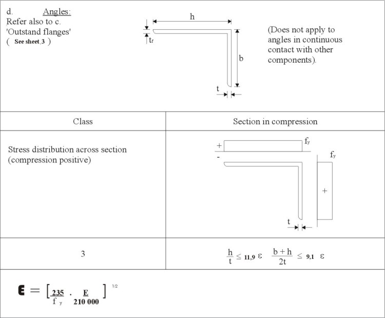
The classification of cross-sections according to their ability to resist local buckling and to sustain load with deformation has proved a useful concept for the design of carbon steel members. Four classifications are recognised:
Class 1: cross-sections able to develop the plastic moment of resistance with rotation capacity.
Class 2: cross-sections able to develop the plastic moment of resistance without rotation capacity.
Class 3: cross-sections able to develop the yield moment.
Class 4: cross-sections unable to reach the yield moment due to local buckling.
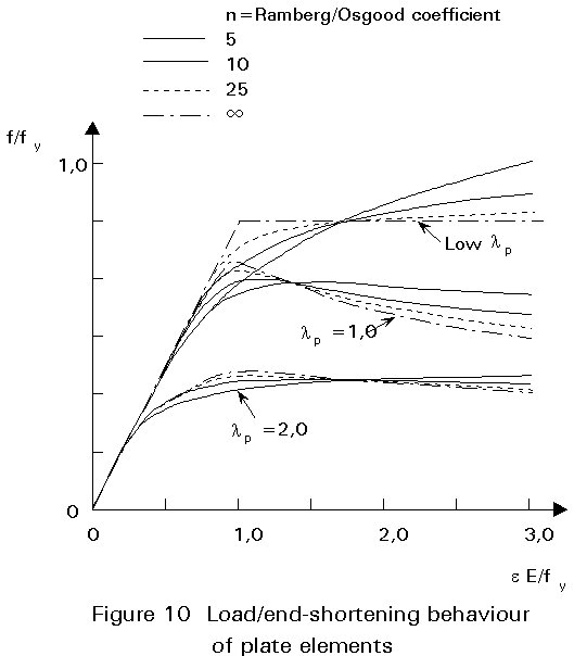
The classification of a cross-section depends on the most unfavourable plate element within the cross-section. The load/end shortening behaviour of an element is dependent on its slenderness:
![]() p
p
in which b/t is the plate width to thickness ratio
e = 
ks is the buckling factor.
Table 1 gives the maximum width-to-thickness ratios for compression element classification, according to Eurocode 3, Annex S[4]. However, numerical data for plate elements, Figure 10, indicate that strain hardening materials exhibit longer plateaus and less steep unloading characteristics than non-hardening materials such as carbon steel. Thus, if a carbon steel element may be classified as a Class 1 element, then a stainless steel element of the same slenderness has at least as great a deformation capacity and can likewise be classified as Class 1.
Class 3 element limiting ratios are found from the slenderness at which the local buckling curve (see below) just reaches yield. These ratios are lower for stainless steel than for carbon steel. It may be noted that with lower Class 3 limits, but with the same Class 1 limits, a smaller range between Class 1 and 3 exists for stainless steel than for carbon steel. There even exists the possibility that Classes 1 and 2 could collapse to a single class for stainless steel, though this potential simplification is for future research.
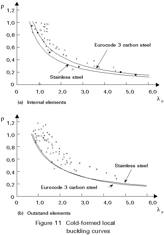
As with carbon steel elements, the effects of local buckling may be accounted for in design by the use of the effective width approach. Whereas only one formulation is used in Eurocode 3 for carbon steel, three design curves are proposed in Eurocode 3, Annex S[4] for stainless steel following a review of available data:
beff/b = 0,83 / (![]() p + 0,29)
for all internal elements such as webs or flanges bounded by pairs of webs.
p + 0,29)
for all internal elements such as webs or flanges bounded by pairs of webs.
beff/b = 1,09 / (![]() p + 0,45)
for cold-formed outstand elements.
p + 0,45)
for cold-formed outstand elements.
beff/b = 1,10 / (![]() p + 0,51)
for welded outstand elements.
p + 0,51)
for welded outstand elements.
Figure 11 shows the experimental data and design curves for cold-formed elements.
There are two main differences between the design of hot-rolled carbon steel members and stainless steel members:
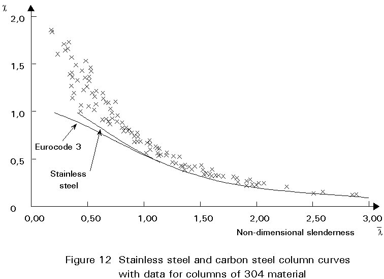
i. The effect of material non-linearity means that slightly different design curves should be used for stainless steel. This point has been discussed in qualitative terms in Section 4.1.2 above. For flexural buckling of cold-formed sections a more generous design curve is recommended in Eurocode 3 for stainless steel, see Figure 12 which also contains experimental data. The high strength at cold-formed corners allows the use of a more generous curve. On the other hand, austenitic stainless steel welded columns should be designed to a lower curve than that used for carbon steel, due to the higher welding residual stresses in stainless steel, mentioned in Section 3.4.
ii. It has already been noted in Section 2.3 that greater use will be made of cold-formed sections in stainless steel than would be usual for carbon steel. The designer will therefore more often have to consider buckling modes other than flexural buckling, i.e. torsional and torsional-flexural buckling. The limited evidence available does not suggest that stainless steel columns behave any worse than carbon steel columns in these buckling modes.
As for columns, beam design in stainless steel uses similar checks to those used for carbon steel beams, but different buckling curves are used for stainless steel. Thus, for lateral-torsional buckling, the next lower buckling curve to carbon steel should be used for stainless steel.
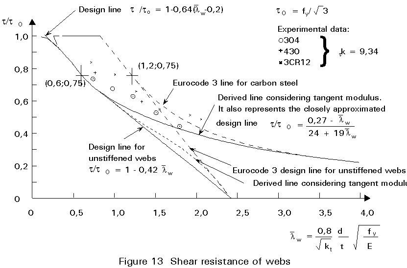
One of the greatest differences observed between carbon steel and stainless steel concerns web shear buckling. Figure 13 illustrates Eurocode 3 design curves for carbon steel and the recommended design curves for stainless steel. The latter are close approximations to analytical curves derived from the carbon steel curves by using the tangent modulus approach described in Section 4.1.2. The derived stainless steel curves are a satisfactory lower bound to the available experimental data.
The accurate calculation of the deflections of members composed of stainless steel materials is a complex matter. The shape of the load deflection curve is affected by the non-linear stress-strain relationship of the material and may be influenced by local buckling effects in the compression flange. Whereas in the case of carbon steel members the modulus is constant (i.e.equal to Young's modulus) down the beam depth and along the length of the beam, for stainless steel members the (tangent) modulus may vary throughout the beam according to the value of stress at each point. An accurate deflection calculation generally requires the use of iterative techniques which are unsuitable for design. Furthermore, uncertainties in end restraint, element thicknesses, material behaviour, let alone the loading, suggest that it is unrealistic to expect or seek mathematical exactitude in estimating deflections. It is therefore appropriate to use approximate techniques such as replacing Young's modulus by the average of the secant moduli in the tension and compression flanges.
As for the design of members, the design of stainless steel connections is very similar to the design of carbon steel connections. Although standardised details can be advantageous for carbon steel structures, the greater material cost of stainless steel favours a move away from uniformity of details as a way of reducing such costs even if increased labour charges result.
Connections work, even where the assumed load path is not actually realised, because of steel's great ductility and hence the potential for redistribution. In this respect stainless steel, and particularly the austenitic grades, is superior to carbon steel.
All forms of connection used for carbon steel may also be used with stainless steel except for joints made with friction grip bolts. Friction grip bolted joints are not made in stainless steel because of the low coefficients of friction for stainless steel, stress relaxation in stainless steel bolts and the variable torque characteristics of stainless steel bolts.
The ultimate limit state of stainless steel bolted connections can be obtained by reference to the provisions in Eurocode 3 for carbon steel connections. However, because stainless steel has high ductility and because ratios of material yield to ultimate strength are low, serviceability criteria are more important for bolted connections in stainless steel than in carbon steel. There are two aspects to consider:
Bearing Resistance
The ultimate resistance in the equation for bearing resistance is obtained using fu equal to the ultimate strength of the connected ply. However, the useful resistance of a bolted connection in stainless steel is usually governed by serviceability criteria in which the hole elongation at serviceability loads is to be limited. In order to avoid carrying out a separate check for serviceability it is recommended to place a limit on hole elongation at ultimate load by using a reduced value of fu, i.e. fu¢ .
To limit hole elongation at ultimate load:
fu¢ = 0,5 fy + 0,6 fu
Bolt Tension Resistance
This aspect particularly applies to bolts in the annealed condition, i.e. bolts of Property Class 50 - see Lecture 18.1, because the ratio of yield to ultimate strength is low (= 0,42). Resistances determined according to Eurocode 3[5] are based on the ultimate strength of bolts. This basis leads to bolts of Property Class 50 being stressed above yield at working loads. It is recommended in Eurocode 3, Annex S[4] to take the basic strength fub of a stainless steel fastener as follows:
fub = specified minimum value for the tensile strength but no more than 1,9 fyb
fyb = stress at 0,2% permanent strain.
Given that appropriate consumables are selected to give weld metal yield and ultimate strengths at least equal to those of the parent metal, then the provisions of Eurocode 3 can be applied for calculating resistances of welded connections.
The potential for corrosion should be recognised and for this reason intermittent welding should preferably be avoided. Caution should also be exercised with partial penetration butt welds due to the possibility of capillary action and subsequent crevice corrosion occurring.
In common with other metals and alloys, stainless steel suffers from distortion on welding. The distribution can be greater in the case of austenitic stainless steels, see Section 3.4 above. It may lead to fit up problems during assembly. Welding distortion can only be controlled, not eliminated. The following actions may be taken by the designer and the fabricator:
a. Designer actions
× Remove the necessity to weld.
× Reduce the extent of welding.
× Reduce the area of welds. For instance in thick sections, specify double V, U or double U preparations in preference to single V.
× Use symmetrical joints.
× Design to accommodate wider dimensional tolerances.
b. Fabricator actions
× Use efficient clamping jigs. If possible the jig should incorporate copper or aluminium bars to help conduct heat away from the weld area.
× When efficient jigging is not possible, use closely spaced tack welds laid in a balanced sequence.
× Ensure that good fit up and alignment is obtained prior to welding.
× Use the lowest heat input commensurate with the selected weld process.
× Use balanced welding and appropriate sequences, e.g. backstepping and block sequences.
The essential differences in the structural behaviour of stainless steel and carbon steel are:
[1] Dier, A.F., "Design Manual for Structural Stainless Steel", EURO INOX, 1993 (in press).
[2] Tendo, M., Takeshite, T., Nakazawa, T. and Abo, H., "Room Temperature Creep Behaviour of Austenitic Stainless Steels", International Conference on Stainless Steels, June 1991, Iron and Steel Institute of Japan.
[3] ANSI/ASCE-8-90: Specification for the Design of Cold-Formed Stainless Steel Structural Members, American Society of Civil Engineers. ASCE, 345 East 47 Street, New York 10017-2398, USA, July 1991.
[4] Eurocode 3: "Design of Steel Structures". Part 1: Annex S: Use of Stainless Steel (in preparation).
[5] Eurocode 3: "Design of Steel Structures": ENV1993-1-1: Part 1.1, General rules and rules for buildings, CEN, 1992.
Table 1 (Sheet 1). Maximum width-to thickness ratios for compression elements
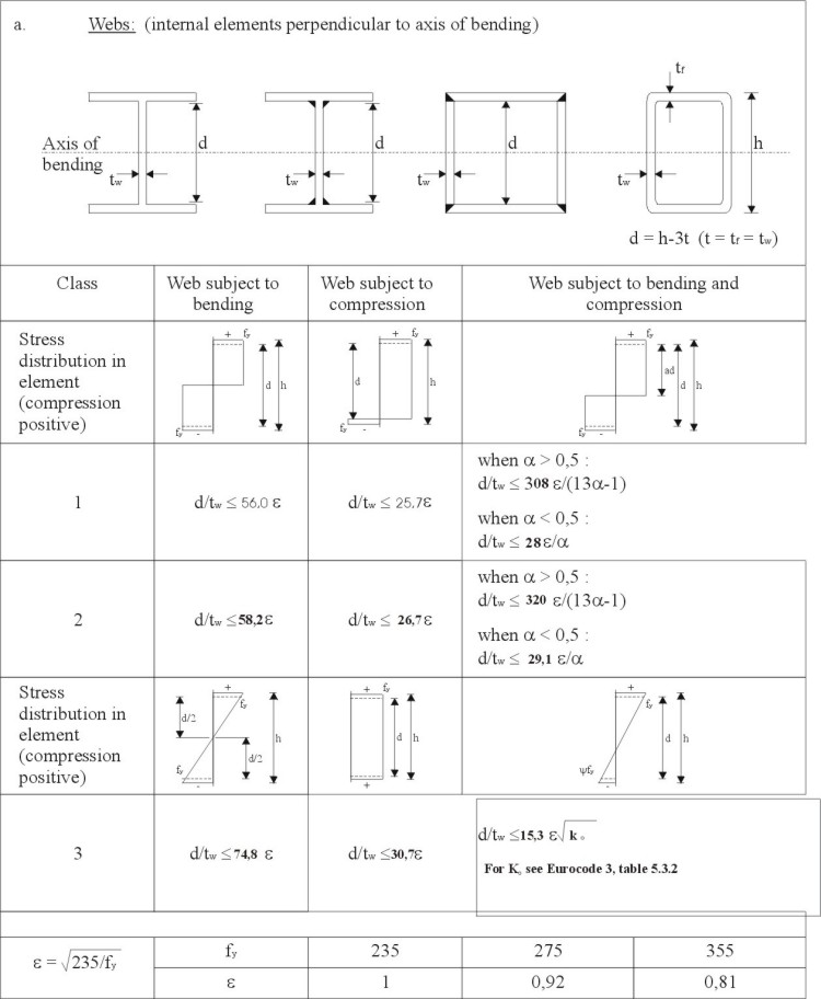
Table 1 (Sheet 2). Maximum width-to thickness ratios for compression elements

Table 1 (Sheet 3). Maximum width-to thickness ratios for compression elements
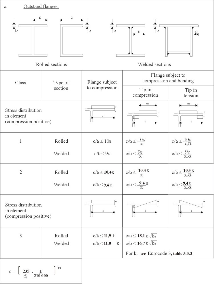
Table 1. Maximum width-to thickness ratios for compression elements