ESDEP WG 16
STRUCTURAL SYSTEMS: REFURBISHMENT
To describe the nature of constructing new building interiors behind a retained facade or maintaining an existing interior structure and replacing loadbearing elements of the facade.
None
Lecture 16.1: Strengthening of Structures
Lecture 16.2: Transformation and Repair
Restructuring a building generally involves replacing the internal loadbearing structural elements whilst retaining the facade, although in some cases it might be the external structure which is replaced as part of a new cladding treatment. Such work requires careful consideration of the programme of construction and, in particular, the relationship between temporary and permanent work. The range of temporary works typically used in such projects is described in Lecture 16.1. Where permanent features can be introduced at an early stage to stabilise the retained parts of the building, it may be possible to achieve some cost savings. Connections between the existing fabric and the new work, both temporary and permanent, need to be carefully designed, particularly with regard to loadings imposed on the retained structure and the effect of deformations of the new work on existing material, which may be fragile and brittle. At the same time, sufficient lateral rigidity must be provided to ensure stability. These principles are illustrated with a number of case studies.
As discussed in Lecture 16.2, there are many reasons for refurbishing a building. In some cases the refurbishment is so extensive that only the original facade remains, the interior being totally reconstructed. This work might be described as restructuring and represents the most extensive form of repair or reconstruction activity associated with existing buildings. Although it is generally more expensive than total demolition and new construction, it may be economically viable due to local planning or tax incentives. For instance, in the United Kingdom buildings originally built before the 1940s can qualify for an increase in the plot ratio allowing a larger lettable area than the equivalent new build structure on the same site. In the case of a building in Finsbury Square in London, two extra floors were added at roof level providing an increase in the lettable area for the client. Obviously the economics of the more costly solution of restructuring needs to be considered against the option of starting again from scratch but achieving a smaller lettable area.
Another important reason for restructuring rather than rebuilding is where the facades are of architectural or historical interest, or where there are requirements for maintaining the existing character and appearance of an area.
In Europe many buildings which are being refurbished are basically of masonry construction with relatively low floor-to-ceiling height. The need to retain the existing facade is usually of greater importance to the planners than the retention of the interior structure. This type of refurbishment can mean costly temporary works for restraining the existing facade as described in Lecture 16.1. In other cases it may be the internal structure which is maintained whilst modifications are made to the facade.
In this lecture the construction principles of restructuring are discussed and some typical examples described. They illustrate how steel can be used to satisfy both the structural and architectural requirements.
The essential principles of restructuring buildings are similar to those of any new construction, although the constraints of the existing facade in terms of size and details, such as window positions and suitable points for connecting back to the new internal structure, will clearly influence the new structural layout and form. Particular care must be given to the sequence of construction because of the need to restrain the facade at all times and to ensure that any temporary works do not obstruct permanent installations.
If the existing facade is of a sufficiently robust construction it may be feasible to re-use it to carry horizontal wind forces and to provide stability to the new frame. However, buildings built with poor quality bricks and mortar may be unable to provide sufficient strength to carry new forces and hence additional stabilising systems may be required.
Diagonal bracing is often the most efficient way of providing stability to the new structure and, as in conventional construction, it can be located around the stair/lift core. If space for diagonal bracing is limited, rigid frame construction can be used, although it is less efficient. Alternatively, use can be made of steel plates as vertical cantilevers.
In refurbishment the existing facade may be of a fairly fragile material and deflections need to be limited to avoid excessive cracking. The deflection requirements of the frame often take precedence over the stress design and in rigid frame construction larger columns may be required to limit horizontal movement.
The use of prefabricated steel staircases facilitates access and improves speed of reconstruction.
The normal procedure is to provide temporary support to the facades as described in Lecture 16.1. The internal structure can then be carefully demolished and removed from site. The new structural frame can then be erected but particular care needs to be given to the size of elements which can be handled since the site will inevitably be a restricted one and access may be difficult. The location of the temporary bracing system for the facade will also create an obstruction.
Any type of floor can be conveniently used in refurbishment, although overall floor depth may be critical. Existing storey heights must often be maintained to suit window arrangements; this requirement may limit the overall floor zone and, if extensive servicing is to be installed, reduces the space available for the structure.
Timber joists may be appropriate where the internal character of the building requires it. Because of shrinkage or movement, the timber should not be relied on as giving lateral restraint to the steel beams and provision of fire resistance needs consideration.
Precast floor units can be used either sitting on the top flange of the steel members or onto a shelf angle. The latter position reduces the overall depth of the floor facilitating the accommodation of services where the storey height may be critical.
Steel metal decking offers the same advantages in restructuring as in new building. Composite action can be achieved through the use of through-deck stud welding. Where the welding is not permitted on site, pre-welded studs can be fitted during fabrication and the decks either installed in short lengths or drilled to allow them to drop over the shear studs. In either case, composite action can be achieved. Fire resistance can be provided using secondary reinforcement in the concrete topping. Existing and new parts of the structure can be conveniently tied together through the use of loose reinforcing bars. In addition, the decking is easy to cut on site with a disc cutter and hence can be fitted into any irregularities in the existing facade or around obstructions which may be found on site.
The limit on floor construction depth imposed by existing window heights may be critical and the structural system needs to take account of the service requirements. A two-way spanning grid of steel beams can be used with services spanning parallel to the primary beams and crossing over at higher level parallel to the secondary beams.
Once the internal structure has been at least partially completed, it will be necessary to form a permanent connection to the retained facade. The precise detail adopted will depend on whether any vertical loads are to be transferred from the new structure to the facade.
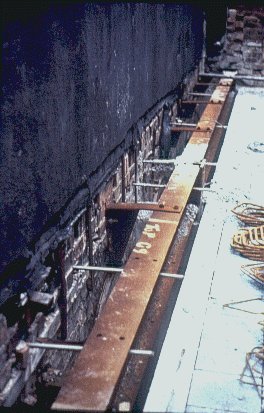
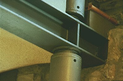
The usual approach for connecting the new steelwork to the existing facade is to use rag bolts cast in concrete padstones set into the wall. However, on shrinkable soils such as clay, the question of foundation movement may need to be considered. The existing facade will have been carrying load for some years resulting in settlement of the foundations. Once the load on the facade is relieved and transferred to the internal steel structure, the soil may recover and the foundation to the existing facade start to rise. At the same time, the new foundations will start to settle imposing differential movement between the frame and the facade. The detail normally adopted is to form a connection between the wall and the perimeter beams which has some flexibility in the vertical direction. One simple way of doing this is to use a flat plate (Slide 1).
Slide 1 : Connection between new steel frame and existing facade using a flat plate.
If it is not possible to provide sufficient connection to the perimeter beams, it may be necessary to connect the facade to the column. This connection can be achieved through the use of angle sections welded either side of the column and bolted into the facade using epoxy resin anchors (Slide 2).
Slide 2 : Connection between a new steel column and an existing two storey brick pier using twin angles.
Alternatively, the facade can be 'tied through' using stainless steel rods and washers. The rods are installed through oversized holes drilled in the facade and pockets on the outside accommodate the nut and the washer plates. Internally movement is allowed vertically by the oversized hole; horizontal restraint is provided by the clamping action through the nuts at either end of the rod. The main problem with this technique is the need to make good, which on complicated facades with intricate details can be an expensive operation.
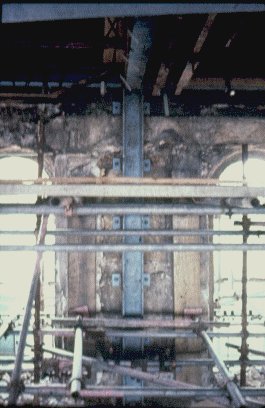
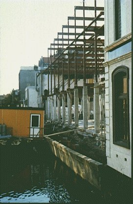
The steel frames used to support the facades can be incorporated as part of the final works. This operation might typically involve installing the columns prior to demolition (Slide 3). Temporary angle bracing may be provided if necessary and the floor beams can be installed immediately above the existing floor level if this suits the final planning. Temporary connections can be made between the steel floor beams and the facade in the form of a gallows bracket.

Slide 3 : Installation of the columns prior to demolition. Temporary angle bracing has been provided.
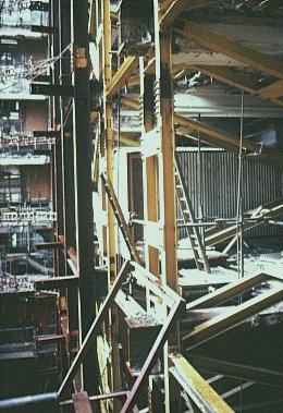
Demolition of the internal floors and walls can then take place (Slide 4), the retained portion of the facade being restrained by the frame which has been installed.
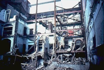
Slide 4 : Demolition of existing internal structure after partial installation of new steel frame.
Once the demolition is complete and the site has been cleared, the reconstruction of the remainder of the building can take place (Slide 5). The internal perimeter bay which provided the temporary works is also part of the final frame structure. The adoption of this method can save a considerable amount of cost to the developer.
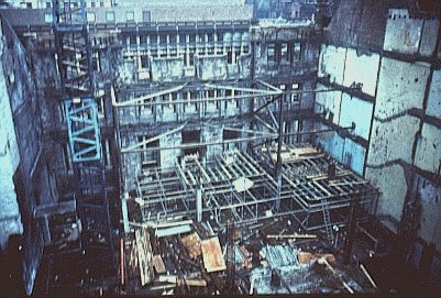
Slide 5 : Once the demolition is complete and the site has been cleared, the reconstruction can proceed.
If the existing structure is a steel frame it may be possible to retain the first perimeter bay of steelwork attached to the facade, providing additional temporary diagonal bracing as necessary; the remainder of the internal structure can then be removed. This procedure means that, as far as the facade is concerned, it is still connected to the structural framing and does not require any further temporary works. The diagonal bracing which is provided to stabilise the frame whilst the interior is removed is easily cut out after the contract is complete and is a relatively cheap way of providing temporary works.
It may be that a combined approach is required. In the case of the rebuilding of the Waring and Gillow's store in London, the old facade was retained by a 700ft temporary structure consisting of 300 x 300 UC columns braced with channel sections forming a self-supporting structure located within the building perimeter. This structure enabled the facade and a 5m wide zone behind it to be preserved intact while the remaining part of the building was demolished. After rebuilding the inside in accordance with a new, more functional layout, providing 14,800 m² of modern office space, the steel structure was gradually removed [1].
If the perimeter columns are in a position which is unacceptable to the architectural planning of the building then it is possible with a steel frame to reposition them. Repositioning typically involves constructing a temporary cradle support to the internal beams allowing the perimeter columns to be removed (Slide 6). The new columns may then be attached to the steel beam, in this case through the use of angle cleats, and carried on a new foundation.
Slide 6 : Refurbishment project in Edinburgh, UK
The same principles of efficient construction for new building also relate to refurbishment and, in some aspects, are even more critical. Once the site is clear and a new frame is ready to be inserted, it is often possible to pre-assemble steel elements on site to speed up the erection process. Frame assemblies can be erected in multi-storey height sections. Attaching ladders and bolt bags (for additional beam connections) to the column prior to lifting into place allows for readier access and quicker construction. The whole unit is then lifted inside the facade and fixed into position.
The advantages of steelwork are that it does not suffer from shrinkage or creep and does not need to cure before it can carry loads. The only considerations which need to be made are of strength and sizing and of deflection. The need to limit the deflection of the steel members to avoid cracking delicate facades which are being carried is obvious. The usual method is either to pre-camber the steelwork or to use folding wedges to create initial deflections prior to packing up with brickwork or mortar.
After restoration, the former working quarters of Essen-Werden Abbey housed the canteen, cafeteria, a stage for experimental art and rehearsal rooms. Little of the historic building was left unchanged. The roof framework was dismantled and the building was completely gutted. Only the exterior walls were left.
The new fittings - towers, staircases, galleries and terraces were inserted as independent structural units within the confines of the existing right-angled walls, completely detached from the outer shell.
The new construction is laid out in such a way that the only loadings imposed on the existing exterior walls are those from dead weight and wind (Slide 7). The vertical loads are carried by a steel skeleton, whereas the horizontal loads are carried by the reinforced concrete cores close to the main entrance, bracing the whole building.
Slide 7 : Folkwang School, Essen-Werden, Germany
The roof framework remains visible from the inside in the area of the studio, the experimental stage and the hall. The roof loads are carried by rafters and purlins and transferred by the ridge and centre purlins to a latticework strut frame in the transverse axes of the building. The strut frame finally transfers the vertical loads via the columns into the ground. Bracing is provided by horizontal cross-tie trusses out of steel tubes to bear the horizontal roof loads. The bracing out of the roof itself is achieved by transverse strut frames and in the longitudinal direction by hip rafters.
The building is a convent belonging to the sorority of St Elizabeth. The duties of the convent include running a children's home which is in the care of the sisters of the Order. Since the 1970s it had been found that the available space no longer sufficed to cope with needs, so it was decided to rebuild the children's home. The old wing was designated to become the home of the sisters.
As the room lay-out in the old wing was not suitable for its newly designated function and the interiors were in a rather advanced state of decay, the decision was taken to gut the building and totally renovate it.
As both the old decorative facades and the roof construction were to be left unchanged, materials could only be brought in through relatively small window or door openings, making the use of I-sections particularly suitable.
The existing floors were dismantled in sequence and replaced by new beams HE 300 B or HE 400 B (Slide 8). These floor beams, which act compositely with the concrete floor slab, bear on the external masonry walls which are up to 70cm thick. Where this bearing was located directly above a window opening, a transverse girder (HE 200 A) was inserted into the masonry over the window lintel in order to transfer the beam loads.
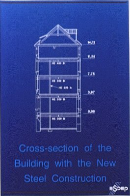
Slide 8 : "Kannerland", Limpertsberg, Luxembourg
During construction, the following measures were taken to stabilise the building and new steel construction:
These measures were temporary and the individual elements were removed after the concrete had set and the stabilising partition walls had been constructed.
In order to protect the steel construction from fire, the HE 200 A columns were covered with expanded metal and built into the surrounding brickwork (24cm). The floor beams are protected by fire-resistant, suspended ceiling boards.
With a useable surface area of 1,500m² the new sisters' home accommodates, amongst others, 18 living rooms, 2 stairwells and a lift shaft, a refectory with a kitchen as well as a small chapel with a sacristy and confessional on the first floor.
The refurbishment of the Roemerhof in Zurich follows a very similar pattern to that of Kannerland described above. The building is of notable architectural merit built at the end of the last century. To solve the ever increasing problems of space, the Bank considered two alternatives: demolishing the building and re-building a new one, or restructuring the existing building, giving its interior a more rational layout and leaving the facade unchanged. The second alternative prevailed: it was certainly more valid from a cultural point of view and moreover it enabled business to continue in the office during the work thanks to a very detailed programme of operations.
The inside was completely stripped and replaced by a steel skeleton braced by the stair and lift cores. The various construction stages took place as follows:
The use of a steel framework resulted in a significant reduction in the weight of the structure, with consequently lighter foundations. Thanks to the speed of erection it also enabled the schedule to be achieved with minimal interference to business activity.
This project involved the renovation and extension of a former department store originally built in 1934. This department store, designed by the architect JDulker for the Winter fashion chain, was itself a partial renovation of a former technical school. The building had been allowed to deteriorate from about 1968 and had stood empty from 1975 until this renovation in 1982. The particular interest in this project is the re-use of the existing steel structure with a new steel facade.
The history of the building had played an important role in the design. The central idea was not primarily to make a building which would take up a discrete position in the street, but to take further the ideas suggested by architect Duiker in 1934: the construction of a metal facade.
The facade is of steel construction separate from the skeleton. The outer skin is made up of horizontal steel boxes filled with mineral wool. The exterior is covered with vertical panels, finished in a factory applied grey coating. The interior is finished with enamelled steel plating, which also contains the heating elements. The window frames and the shop front frames are of anodized aluminium.
The existing structure consisted of steel beams and columns, placed on the existing foundations of the former technical school. For this renovation the steel covering and the wood joists were removed. In order to make the building more practical and to make an extra floor, the following construction operations were carried out:
Slide 9 : Weteringschans 165, Amsterdam
By extending the existing 3rd floor and by adding a new 4th floor it was thus possible to increase the useable area from 2.150 to 3.140m².
This building was completely gutted and restructured to house the new court offices. The arrangement of the windows, cornices and all ornaments in the masonry facades characterising its neo-renaissance style was preserved.
The main load-bearing structure consists of four reinforced concrete towers 9m x 9m, containing stairs, lifts and floor services and located at the corners of the inner covered courtyard. These towers provide the vertical support to the roof and the five floors suspended from it, as well as horizontal stability to resist the effects of seismic activity (Slide 10).
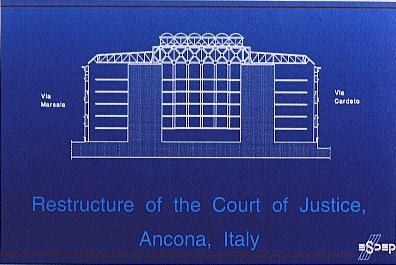
Slide 10 : Court of Justice, Ancona, Italy
The system of suspension in the roof consists of four pairs of truss girders supported on the inside edge of the four reinforced concrete towers, thus marking the perimeter of the covered courtyard. Each pair of trusses forms a box girder 1,80m wide, 4m high with cross members at 3,0m centres and X-shaped wall diagonals. All the truss members (chords, vertical and diagonal bars) are made of steel I-sections, connected by means of bolted gusset plates. The inner ring made up of four pairs of girders with a span of 21,40m represents the key component of the steel skeleton which the other members of the structure are connected to:
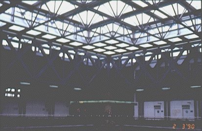
Slide 11 : Court of Justice, Ancona, Italy
The five floors suspended from the roof girders are associated with the four zones of approximately 9 ´ 20m between the four towers (Slide 12). They consist of structural steel beams and joists supporting composite metal deck floor slabs. The main beams on the interior side are suspended by tie rods from the box girder ring, whilst on the outer side they rest on the reinforced concrete structures forming the perimeter area between the four towers and the exterior facades of the building. They were connected by welding to suitable plates pre-set in the concrete. All the other structural components were assembled on site with bolted connections. The individual elements were fabricated in sizes convenient for transportation inside the historic city centre and erection within a densely built area.

Slide 12 : Court of Justice, Ancona, Italy
[1] 'Something Old ...', Building with Steel, Vol. , No. 4, April 1979, Constrado.
[2] 'Refurbishment', ARBED, Luxembourg 1989.