ESDEP WG 16
STRUCTURAL SYSTEMS: REFURBISHMENT
To discuss the need for refurbishing existing buildings and the various forms of structural alteration which might be associated with such works. To highlight particular issues which need to be considered in refurbishment as distinct from new construction, and to illustrate the principles by a number of case studies.
None.
Lecture 16.1: Strengthening of Structures
Lecture 16.3: Re-use of Buildings
Refurbishment of buildings is becoming increasingly common, to enable the provision of modern facilities within old buildings, to retain buildings of architectural merit, and because it may be less expensive than new build. The degree of refurbishment can vary enormously from simple refitting to altering the existing structure, including gutting and extending both upwards and sideways. Attention must be given to the special planning, design and construction needs of refurbishment projects. These needs are described in principle and illustrated by a number of case studies. The particular role of structural steelwork in these activities is highlighted.
The life of a building is not unlimited. However, the typical building frame is expected to last a good deal longer than other parts of the building. The life may typically amount to some 60 years for the frame whilst the cladding is expected to last 30 years, services 20 years, interiors five years and communications and control equipment as little as two years. The need to allow flexibility and provide adaptability in the building frame is, therefore, of critical importance not only at the refurbishment stage but also when the building is initially designed. The design team should consider this requirement carefully at the new build stage so that when faced with subsequent refurbishing the necessary alterations can be easily accommodated. When faced with an existing steel frame which has been properly planned and constructed, the option of refurbishment may be very straightforward. For example, typical American steel framed buildings have large spans from a core area to the external wall with sufficient height having been allowed at the initial building stage for services to run under the steel beams; hence modifying services and interiors is straightforward. In such cases refurbishment may involve little more than an internal refit and recladding, the existing masonry being removed and replaced with a new lightweight, glazed facade.
There are may reasons for deciding to refurbish a building. The service/communications equipment may be out of date with regard to user requirements; the building may need updating to generate a demand for tenants, or may need major remedial works to suit new needs. Finally it may be more economically viable to refurbish rather than rebuild, and this may be influenced by local planning and tax incentives. For instance in the United Kingdom buildings originally constructed before the 1940s can qualify for an increase in the plot ratio allowing a larger lettable area than the equivalent new build structure on the same site. In the case of a building in Finsbury Square, London two extra floors have been added at roof level providing an increase in the lettable area for the client. Clearly the economics of refurbishment, often a more costly solution, need to be considered against the option of starting afresh but achieving a smaller lettable area. It may also be that other factors such as 'listing' of historical facades and structures or requirements for keeping the character of an area will force the design team into a refurbishment option.
Steelwork is widely used in the transformation and repair of existing buildings. The main categories of structural alteration (as distinct from repair and strengthening which, together with temporary works, were discussed in Lecture 16.1, and complete restructuring which is considered in Lecture 16.3) are gutting, insertion, extension (vertical and horizontal), and reducing dead load.
These categories are described in principle in the following sections, highlighting how structural steel in particular may be used in such operations. A number of case studies are described to illustrate how these principles have been applied in real situations. In practice the distinction between these categories inevitably becomes blurred and this can be seen in the examples cited.
Gutting consists of the removal of the internal structures of a building and substitution by others of a different type. It may be necessary due to changes in use of the building requiring modifications to the structural form, for instance the replacement of loadbearing walls by a structural frame. The most extreme cases arise when architectural and/or town-planning considerations require the conservation of the facades of a building whilst the layout of the interior is completely changed; this case can be defined as restructuring and is dealt with in Lecture 16.3.
Insertion involves the integration of new structures or structural elements within the original overall building volume. Not only does this integration provide additional usable floor space but internal areas can also acquire new features derived both from their more rational layout and from the additional structural elements endowing the building with new stylistic values. The most common example is the creation of a loft within the roof space in order to increase the usable floor area within the limits of a given volume. The self-supporting frames often constructed within museums to house special exhibition show-cases, possibly visible on several levels, as well as the cages of new staircases and lifts, may also be included in this category. In these cases it is important to minimise the effect on the existing structure. Steel is, therefore, very suitable because of its high strength, low weight, simplicity of site construction and the fact that steel structures can be dismantled, if necessary, at a later stage.
Vertical extension consists of adding one or more storeys above the existing structure, resulting in an increase of overall volume of the building. It is necessary to check the loadbearing resistance of the original building, taking account of the additional loads and structure to determine what strengthening, if any, is needed. Again the high mechanical performance (strength/specific weight ratio) of steel makes it most suitable for such purposes because it helps to minimise the weight of the new structure.
Extending a building sideways can largely be treated as new construction since the interaction with the existing structure is largely restricted to the details of the connection. As far as possible the form of the new extension should be consistent with the existing so that column lines coincide, avoiding the need for transfer structures. The loadbearing resistance of existing elements must be checked where they are required to carry additional loads, and if necessary strengthening measures undertaken. Alternatively the new structure can be treated as a totally separate, free-standing form, for instance providing new columns adjacent to the existing to carry new beams.
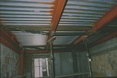
The opposite process - reducing dead load - can include the demolition of one or more levels at the top of a building, for instance to reduce loads on the existing structures. Floors, roofs or other structural elements might also be replaced with lighter materials for the same reason. In fact, the replacement of heavy wooden floors with light steel I-sections and profiled steel decking is very common (Slide 1) as is the complete reconstruction of roofs using steel roof trusses.
Slide 1 : Refurbishment of town centre 'Capidimonte' in Ancona, Italy
It may be possible to refurbish an existing building without making any structural alterations, particularly if the need for adaptability has been considered at the initial design stage. However, in many cases, particularly where a change of use is involved, some structural alterations will be necessary. In any event there will need to be a full survey of the existing building to determine the structural layout and condition [1]. Changes to the structure will be designed to be compatible with any remaining parts of the building. The load carrying resistance will need to be assessed and taken into account, in terms of both strengthening measures (see Lecture 16.1) and changes in load distribution which might result from the proposed alterations.
Construction procedures are probably even more critical in refurbishment contracts than in new building. It will certainly be necessary to consider the stability of the complete building at all stages including demolition and reinstatement. It may also be necessary to consider the needs of the building users if it is to remain even partially occupied during the work.
Roof structures of old buildings are often made from timber trusses, which may have deteriorated due to atmospheric exposure. A suitable solution may be to replace the old timber work with new steel trusses clad with profiled steel sheets.
This system is very frequently used for the roofs of church buildings in southern European countries. In many cases the 'roof' function is combined with that of a diaphragm, which is particularly important in seismic zones. For this purpose a horizontal grillage of steel beams may be created at the level of the bottom tie of the truss in order to provide a rigid connection between the tops of the walls.
Where a monumental building cannot be re-roofed because of the extent of deterioration of the supporting structure, a new roof structure can be made completely independent of the masonry below. This solution has been used to provide a roof over the ruins of the church of St. Rocco in Morra De Sanctis, Avellino, Italy, using a framework of structural steel surmounted by a roof made of trusses and profiled steel sheets [2].
Corrosion of existing steelwork may be a concern in a refurbishment contract. However it is unusual for internal steelwork to suffer significant corrosion defects over the life of the building. Perimeter columns, if kept clear of the outside skin of brickwork, do not usually suffer unduly given a sensible painting system prior to erection. It is often found that these columns have survived without any significant rusting. Corrosion is only likely to be a problem where the steelwork has come into contact with an external skin through which moisture may penetrate. If a clear air flow can be maintained then there should be no corrosion problem, even for steelwork with a fairly unsophisticated paint system.
However there are occasions when poor construction details have resulted in steelwork located in moist, unventilated conditions causing corrosion problems and requiring remedial work.
Guidance on paint systems for the refurbishment of existing steel members is available [3]. The basic approach is to prepare the surface by chipping, scraping or wire brushing, in which case a fairly unsophisticated paint system should be used appropriate to the environment in which the steelwork will be kept. Alternatively if access for more thorough surface preparation using abrasive blast cleaning with either wet or dry abrasives is possible, then more sophisticated modern coatings can be used.
Steel structures have been widely used in the rehabilitation of the entire Capodimonte district of the historic centre of Ancona. The masonry buildings were in an advanced state of decay caused by the extensive damage suffered during the earthquake of 1972 in addition to earlier earthquakes, in particular that of 1930, and the bombardments suffered during the Second World War. This situation had led to the precautionary evacuation of practically all the inhabitants of the district.
In all buildings with two or three storeys above ground floor, the solid brick and dressed stone walls were badly cracked and the mortar had completely decomposed.
A reliable method of restructuring these buildings was needed. The traditional method based on local strengthening of individual components was rejected and instead it was decided to install a new structural system to carry the loads to the foundations. The system developed consisted of steel columns inserted into the perimeter and internal walls, connected to horizontal structures of steel beams and steel decking. The new structure, suitably connected to the reinforced concrete walls of the new stairway cores and also to bracing panel walls, forms an independent structural system with regard to both vertical and horizontal loads.
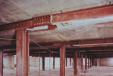
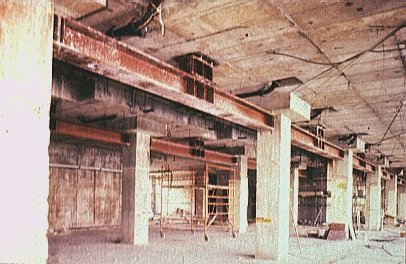
The external walls, suitably restored, still retain their architectural form and provide shelter, but are relieved of any main load carrying function. The internal walls, no longer necessary due to the load carrying resistance of the new structure, and the old staircases were demolished. Small vertical channels were chiselled in the perimeter walls to accommodate the HE 200A columns carrying the main floor beams of HE 220B section. Supported on these are the secondary beams, type IPE 220, with spacings varying from 1m to 1,2m, which in turn support the composite floor slab (Slide 2).
Slide 2 : Section through typical building in Ancona, strengthened by the installation of a new steel frame, comprising HE 200A columns supporting HE 220B main beams.
The roof was reconstructed with trusses and purlins supporting corrugated steel roofing sheets.
The refurbishment works were carried out in the following stages:
Because of the unlimited variability of the buildings, both in plan and in height, it was not possible to forecast accurately the exact length of each individual structural element, and allowance was made for welding all the connections on site.
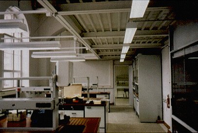
The office building belonging to Van Leer, makers of steel drums and packaging, was built at the end of the 1950s to accommodate about 500 employees. Due to the de-centralization of the Van Leer organisation, only about 300 staff have been working there in the last few years. As with most buildings designed before the oil crisis, energy costs of the building were very high.
The building consisted of a central hall, with a V-shaped two storey office wing at each end. Each office floor had a surface area of about 1.000 square metres. The service rooms were in the central hall and in separate subsidiary buildings. The storey heights were very large: 5,6m gross (4,3m net) in the office wings, while the central hall was 7,2m high.
The loadbearing structure was made of steel with 19 columns in each 1.000 square metre wing at a frame spacing of 8,0m. The distance between columns varied due to the form of the ground plan, from 8,15 to 9,0m. The columns stand about 3m free of the walls. The facade uprights, where the window frames and sun filters were fitted, were free of the floors. When the building was originally designed, the possibility of adding an extra floor to the end wings at a later stage was taken into account for the foundations and construction.
The main requirements of the refurbishment programme were:
·
reducing the storey height in the office wings from 5,6m to 3,75m, so that within the existing building volume the useful office floor space could be increased from 4.000 square metres to 6.000 square metres;·
the design of a new, completely insulated facade, but retaining the original expression of the building;·
the creation of new utility provisions in both wings, such as lift, stairs and toilets.The following solution was adopted for the first phase:
·
fit the steel structure for the new floor at 8,25m;·
assemble the temporary support construction under the new structure;·
shorten the bottom columns by 1,85m, storing the cut column lengths;·
position the jacks;·
release the jack pressure and allow the floor to be lowered by 1,85m;·
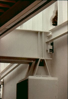
replace the column sections and weld the whole structure together.This procedure is illustrated in Slide 3 and is described in more detail below.
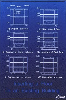
Slide 3 : Refurbishment of the Van Leer Office Building in Amstelveen, Netherlands
The outer wall frames were completely removed, only the supporting uprights remaining. As described above, the new floor (at 8,25m level) was constructed first. All beams, except the overhang beams, were brought up by crane to the existing floor at 6,6m. The overhang beams were bolted directly to the existing columns.
A special mobile tackle was made for fitting the other floor beams. The beams had to be raised about 1,65m to be assembled at the right height. This is an ideal situation - the beams do not have to be raised far and ladders and scaffolding are not required.
After the temporary structure had been positioned and the jack column fastened to the existing column, a start could be made on cutting the main columns using oxy-acetylene. This work had to be done very carefully. The cut had to be absolutely horizontal as the column sections were to be used again on the upper floor, and as little material as possible was to be removed. This cutting and removal of the column sections was the most important process in the whole operation, as at this time the support structure was under maximum load.
When all jacks were in place, the connection bolts between the existing floor and the uprights were released. The jacks were pressurized and the whole construction was raised a little. Then the existing columns were cut and the support structure placed under load again. This was done to eliminate the lowering that would occur when the lower columns were removed. The floor was jacked 1,85m down and set on the shortened columns on the ground floor.
It took three hours to lower the floor the necessary 1,85m - an imperceptible average speed of 1cm per minute. The column joints were welded immediately after the jacks were removed.
The column sections removed in the earlier phase were shortened and fitted with a top plate. These sections were then repositioned between the lowered floor and the new floor. All joints were welded. When the welding was complete, the support construction could be removed and a start made on raising the prefabricated concrete floor planks for the new floor by crane. Then the cast strips were poured and final building could commence.
The first wing took five and a half months to construct, the second wing was completed within four months.
On the South Bank of the River Thames in London, next to Blackfriars Bridge, stood the Kings Reach Hotel. It was built as an hotel in 1974/1976, but was never finished and stood derelict as an empty shell for some years, all 12 storeys and 28,000 sq m of it. It was bought by Sea Containers House Limited, who had the foresight to see the potential in converting the shell to offices, and the courage to do it.
The original structure was of reinforced concrete construction, partly crosswall and partly flat slab. The structure was founded on piles. Above third floor, crosswalls were located at 3,6m centres, this being the standard bedroom width. The walls extended the full width of the building with only a small corridor opening at each floor. They sat on the thick third floor slab transferring the wall loads onto the columns underneath, which were at the double spacing centres of 7,2m.
The basic need was to remove the crosswalls so that the floors could be opened up for office use. The original river-side elevation had terraced balconies which were no longer required for offices. Additional lifts were required necessitating substantial alteration to two lift/stair cores. Other alterations were required, in particular for the installation of air-conditioning and associated plant rooms.
The building is T-shaped on plan with the long edge, the north wing, facing the River Thames. The south wing is at right angles to the north wing.
Both the north and south wings had the same basic requirement to remove crosswalls. Their removal was achieved by introducing new vertical supports towards the middle of the building and new beams at each floor to carry the floor slabs which were originally supported by the walls which were to be removed. To complete the frame, a length of wall was left at each end of the wall run and these wall lengths became the columns at the building perimeters.
For both wings, rolled steel channels were used for the floor beams. They were erected each side of the wall and pinned up tight to the floor slab (Slide 4). The two interior vertical members acted as conventional columns on the north wing, as there were existing columns underneath to support them. On the south wing there was only one column at the end of the wing beneath third floor; the remaining area was void as this wing straddles a road. In the south wing therefore the central members were in the form of hangers carried by new trusses at roof level, the whole still being supported by the original stiff reinforced concrete box which formed the third to fourth floors and spanned the road.
Slide 4 : Refurbishment of Office Building for Sea Containers Ltd., London, UK
The north wing was easier to design in respect of the internal columns, but the thick third floor slab had to be strengthened using plate girders hung from Macalloy bars drilled and grouted through the concrete shear heads of the columns. These girders supported directly the new columns above (Slide 5).
Slide 5 : Refurbishment of Office Building for Sea Containers Ltd., London, UK
The method and sequence of concrete demolition and new frame insertion was carefully studied. The method of transferring the floor loading from the walls to the new frame was evolved using hydraulic flat jacks. In fact all the floors on any one vertical frame were jacked in one operation, fed from a master pump, the object being to get all the deflections and other frame 'bedding down' movements taken up by the jack movement.
Although reinforced concrete was used in places, the bulk of the new framework was structural steel, and in fact some 2.000 tonnes were used in the conversion. The clear advantage of using steel here is that steel does not suffer from shrinkage or creep and can be inserted without the need for propping, so immediately enabling the structure above to be carried. The only requirements are to consider the elastic deflections, which can be accounted for by either precambering or by jacking down into position.
An old industrial building in Cantu in the province of Como, has been converted into a gymnasium using structural steelwork to achieve a change of layout of the original reinforced concrete structure.
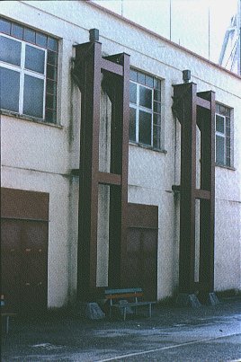
The existing layout consisted of a two-storey reinforced concrete frame with intermediate columns. The conversion to a gymnasium, necessitated completely stripping the interior of the building, eliminating the central columns and intermediate floor. The existing roof structure is now supported by new steel portals arranged in pairs either side of the existing columns and inserted into the external walls. On the front facade, the portals pierce the perimeter walls in such a way as to create an interesting architectural motif relieving the monotony of the facade (Slide 6).
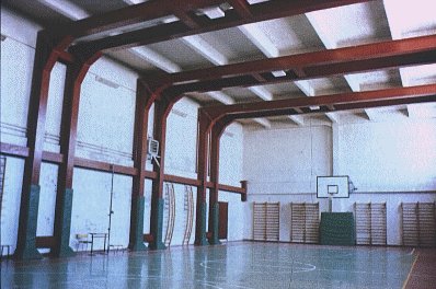
Slide 6 : Conversion of factory into a new gymnasium at Cantu, Italy
Inside, the rafters of the new frame encompass the existing reinforced concrete roof truss and directly support the secondary structures (Slide 7).
Slide 7 : Conversion of factory into a new gymnasium at Cantu, Italy
This building situated at 135 to 145, rue de l'Ourcq and at 24 to 36, rue Labois-Rouillon was an industrial building originally used as a depot and baling plant for old paper and fabric, and later as a furniture warehouse. The property had to be adapted for its new role as an apartment block, whilst making the most of its late 19th Century industrial architecture (Slide 8).
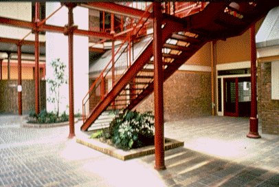
Slide 8 : Rue de l'Ourcq: Inner courtyard
The depth of the building did not allow the whole of the floor area to be used for apartments. It, therefore, proved necessary to form a void in the central section. The architects made use of this constraint to create a unique interior space, strongly defined yet highly differentiated. It formed a kind of backbone which services all of the apartments, allowing them to open onto a quiet garden area away from the noise of the street and providing them with natural daylighting. This arrangement gives the apartments an individual character with a private interior street.
Small business premises have been built on the ground floor, along rue de l'Ourcq and on the little square. This position was chosen because of the easy access and the liveliness that it brings to the street.
All of the floors, beams and columns inside the building built at the beginning of the Century were in an acceptable state with no major damage or excessive corrosion. The structure was very well suited to the change of building use since its components had been originally designed to support heavy industrial loads.
The internal columns supporting the floors are of cast iron construction on a structural grid measuring 4m by 4m. Where the new arrangement created small loads the columns were left in their original condition. For heavy loads the columns were encased in a square section of reinforced concrete. The columns are supported horizontally at mid height by the beams of the mezzanine floors or by the reinforced concrete facade.
The beams were too narrow and some of them were off-centre. In most cases they were arranged in pairs, a flange width apart. Occasionally, a main girder was made up of two beams of different depths. Sometimes the beams were jointed, sometimes single. The connections were as varied as the beams. All the joints have, therefore, been checked and strengthened where necessary and the beam supports at the columns reinforced.
The original floors were made of joists supporting brick and clinker vaults covered with reinforced cement mortar. In certain areas the floor was strengthened by covering with concrete over the whole depth of the joists. In other areas floors had to be demolished or reinforced.
The whole building is covered by a saw-tooth roof arranged parallel to the street. The north slopes were glazed and the south slopes were tiled. The span of the saw-tooth trusses is double that of the floor beams at the lower level. The columns supporting the roof are generally IPN 260 sections.
The conversion to provide the inner courtyard necessitated the removal of several northlights. The orientation of the building and its saw-tooth roof form made it ideal for the installation of solar panels for heating water.
It was necessary to provide a fire resistance of half an hour for the floors and the supporting structure. This fire resistance was achieved in the apartments either by encasing in reinforced concrete approximately 70mm thick where the columns fell within the party walls between apartments or by intumescent paint. In the business premises, rockwool casing (moulded or padded) was used with a protective plaster covering.
The main fabric of the old chemistry building of the Technical University of Berlin, designated a listed building of architectural interest in 1982, was in a good state of repair. However, the interior of the building had suffered greatly from repeated changes of use. The room capacity for the disciplines to be accommodated and for the constantly increasing student numbers was also totally overstretched and only the addition of a new wing and the incorporation of inner courtyards made it possible to disentangle the structures. This transformation was to be achieved as a self-supporting structure in a contemporary architectural style that would nevertheless be in harmony with the existing architectural language of the 19th Century.
The following planning steps were developed:
·
Conversion of the first floor of the front west wing to form three laboratories with a through gallery interconnecting with an existing staircase·
Re-design of the vestibule areas as a prototype for the redevelopment of all common parts·
Reconstruction of a library on the outer west side·
Conversion of the old library area on the third floor into laboratories and surveyor's rooms·
Relocation of the workshops, stores and cafeteria to the inner courtyards·
General renovation of the entire buildingIt was essential to guarantee the continuity of academic activities during the ongoing refurbishment works. A cost estimate had shown that it was more economic to renovate the existing structure than erect a completely new one.
The client's desire for more space was satisfied by fitting a gallery, which was possible thanks to the high ceilings (Slide 9). The gallery is linked to the existing staircases via a light steel bridge (Slide 10).
Slide 9 : TU Berlin, Germany
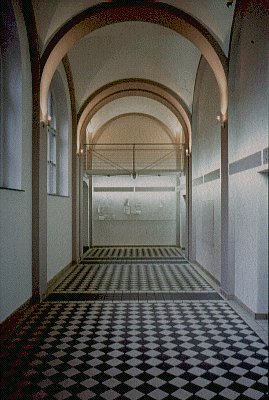
Slide 10 : TU Berlin, Germany
The new elements had been integrated into the existing architecture with great care. Extensive use was made of steel in order to achieve the maximum possible filigree effect and also to relieve the interior appearance. The grid for the steel structure was developed according to the layout of windows and pillars. Transport and erection of the structural elements during the construction phase was greatly facilitated by the use of bolted connections. Thus, for example, on the new gallery a single intersection point serves as a simultaneous connection, between suspension, floor beams, lamp fixtures and parapet.
The corridor is paved in vitrified clay tiles, consistent with existing fragments of the old floor. Tile patterns, lighting and colour schemes enhance the arching and cross-vaulting structures.
Built in 1858, this building was formerly a shed for locomotives before being converted into an exhibition hall in 1987. The refurbishment work aimed to retain the valuable, historic exterior while complementing it with modern architectural concepts. The construction of a new roof for the building was to form the basis for the plan (Slide 11).
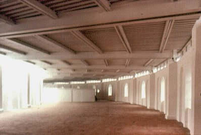
Slide 11 : Reconstruction of Alter Bahnhof, Rosenheim, Germany
In the centre of the building, there is an in-built cabinet-like gallery at a height of 2,7m. As it was required to convert and dismantle this gallery level, a supporting structure made from 114mm diameter hollow section steel columns and HE 140 B beams was chosen.
The connection of the new roof to the existing walls occurred consistently at all contact points via glass elements as fixed or hinged window glazing (Slide 12). The new roof construction consists of IPE 500 I sections laid in pairs, with a span of 15m. Welded angle sections serve to incorporate wiring. In this project, steel did not just prompt thoughts of the railways but rather a material that provides an interesting and aesthetic contrast to heavy masonry.
Slide 12 : Reconstruction of Alter Bahnhof, Rosenheim, Germany
The Paris office of architect Georges Marios is situated in a late 19th Century detached house off the Rue Saint-Jacques with residential accommodation in the attic. In 1988 it was decided to enlarge the building by adding a floor to provide additional accommodation of 130 square metres. The main contractor had to work within two constraints: he was not permitted to interrupt office activities, even when the roof was removed; and the weight of the additional floor had to conform with the existing structure. Hence there was a need for a compromise between stability and lightness, resulting in a steel structural solution within an original system of panel walls made of cellulose fibres.
The existing structure which had not been previously altered, was of traditional masonry form with a sloping tiled roof. The top part of the house was demolished and two new storeys constructed. In order to allow office work to continue uninterrupted, the attic floor was left in place and overlaid with a lightweight reinforced concrete slab to accommodate the increased load and provide a foundation for the new steel structure. This structure comprises peripheral tubular columns, 168mm in diameter and 6,3mm thick, supporting IPE300 edge beams (Slide 13). Floor beams (IPE 360) span approximately 8m between the perimeter structure and the existing masonry.
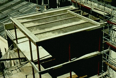
Slide 13 : New steel frame structure at Rue St. Jacques, Paris, France
In order to reduce the weight of the load on the old walls, Georges Marios chose lightweight materials for the facades. These facades were of sandwich construction consisting of 6mm aluminium panelling (fixed on battens with stainless steel screws), a 35mm cavity providing thermal and acoustic insulation, 16mm plywood, 60mm foam insulation and Fermacel inner lining. In all, the new structure weighs a little under 30 tonnes, 8 of which are the weight of the steel structure.
Following a fire in 1983, all that remained of the 13th Century Cistercian abbey were the walls and eleven of the original timber rafters of the chapter house. A plan was formulated to rescue this ancient monument and convert it into an international centre for glass working. The new roof structure had to blend in with the severity and simplicity of the original abbey. This blending was achieved by using steel rafters supported on a curved framework in 193,7mm diameter circular hollow sections (Slide 14).
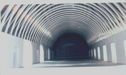
Slide 14 : Abbey of Val Saint- Lambert, Seraing, Belgium
Weathering steel shingles, 3mm thick, are fixed to the rafters by means of self-tapping screws, harmonising well with the colour of the original stonework. Rooflighting is afforded by lines of polycarbonate sheeting of the same size and fixing method as the shingles, arranged either side of the ridge.
The building which houses the Imperial War Museum in London was designed in 1815 by James Lewis as the Bethlem Royal Hospital. In 1983 it was decided to redevelop the building and to provide additional exhibition space by enclosing the courtyard with a glazed roof. Supported on twin tubular columns at 7m centres, the three bay roof consists of two monopitch side spans which cantilever 5,5m beyond the internal row of columns, rather like a crane jib, to support a central barrel vault 12m wide (Slide 15). This structure creates a memorable central space 25m wide, 40m long and rising to about 23m high at the top of the barrel. This area is to accommodate five aircraft suspended from the edge beams of the vault using steel cables. The heaviest of these is the World War II Mosquito at 75kN.
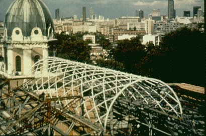
Slide 15 : Imperial War Museum, London, UK
For visual reasons, a single layer diagrid was adopted for the construction of the barrel vault. This structure was analysed as a complete space frame with the supporting cantilevers modelled as springs. A single size of tubular member - 139,7 x 10 CHS - was used for all internal members, with a larger section - 219 x 12,5 CHS - for the perimeter members. Grade 50 steel was used throughout. The design was based on unusually low design stresses because many of the welds were to be carried out on site, and, since tubular members were being used, only partial penetration butt welds could be achieved. An extensive programme of non-destructive testing was undertaken on both shop and site welds.
Because of the importance of both close tolerances and visual appearance, trial assembles were made. The trials included a full assembly of the barrel vault at the fabricators, prior to its delivery to site in twelve separate pieces. On site the roof was assembled on the ground using the same techniques used during the trial, and then jacked into position at a rate of about 3m per hour for connection to the cantilever jibs.
[1] 'Appraisal of Existing Structures', Institution of Structural Engineers, London, 1980.
[2] 'Refurbishment', ARBED 1989
[3] 'Corrosion Protection Guide for Steelwork in Building Refurbishment', British Steel, Teesside 1990.