ESDEP WG 14
STRUCTURAL SYSTEMS: BUILDINGS
To present an example of the design of a multi-storey building relating to the behaviour of beams, columns and connections. Special attention is paid to the influence of the design of the semi-rigid and partial-strength connections on the frame behaviour.
None
Lecture 11.7: Semi-rigid Connections for Buildings
Lecture 14.10: Design of Multi-Storey Frames with Partial Strength and Semi-Rigid Connections
The lecture consists of an example of the design process of a braced frame.
Eurocode 3 provides tools for the design of semi-rigid and partial-strength connections in structures. Calculation methods are given for connection design, and also procedures are presented for taking account of the connection behaviour in the frame analyses.
This lecture will describe the interaction between connection design and frame design. The economic aspects of frame and connection design will be discussed. Taking the (production) costs of the connections into account in the design process will lead to a more economical solution, if compared with a minimum weight frame design.
In this example two software packages are used: The pre-calculation package TVC developed for ECCS by Hoofddorp, the Netherlands, and CASTA/Connections, developed by TNO Building and Construction Research, the Netherlands. The latter package is used to check the connection properties according to Annex J of Eurocode 3 [1].
In Figure 1 the geometry of a braced frame consisting of three storeys and three bays is drawn. For the sake of simplicity the columns in the frame have equal dimensions from the top to the bottom, and the beams have equal dimensions at each floor. The beams at roof site are of different dimension than the other beams. The inner columns differ from the outer columns. In this example it is presumed that the stability against lateral-torsional buckling is ensured. The columns are supported for buckling out-of-plane at floor level. Further it is supposed that no buckling appears in the lower flange of the column. The steel quality is FeE235.
Based on a calculation of loading according to Eurocode 3 [1], it is found that one load case is governing. This load case is drawn in Figure 1.
Design situations may be distinguished as:
The design situations are used for verifications of:
The load data are given in Table 1.
Table 1
|
Ultimate |
Serviceability |
|
|
Roof : Persistent : Accidental |
4,5 kN/m 4,5 kN/m |
3,2 kN/m 3,2 kN/m |
|
Floor : Persistent : Accidental |
13,6 kN/m 13,6 kN/m |
9,1 kN/m 9,1 kN/m |
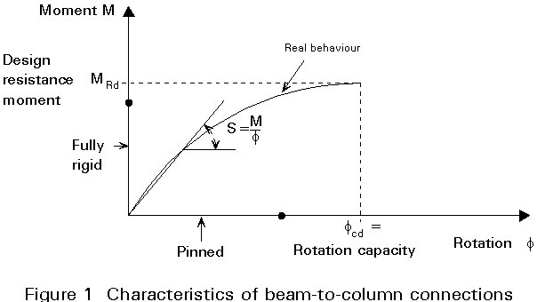
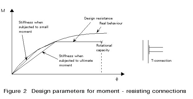
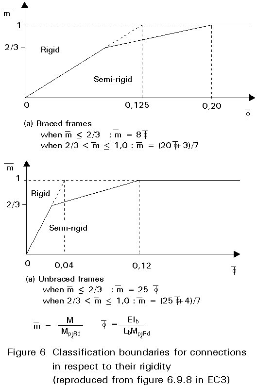
In Eurocode 3, three classes of connections are distinguished (Figure 2). It is a common practice to design a connection either as full-strength and rigid or as nominally pinned, although semi-rigid and partial-strength connections can be an alternative.
In this lecture, the frame is designed first as a simple frame with nominally pinned connections. In a later stage a second and a third design is made. Finally, a variant with rigid and full-strength connections is presented.
A simple design of connections made with cleat angles is given below. The connection is designed for shear resistance. The moment resistance of these connections is negligible.
The floor beams are designed to resist the load using the classical M = 1/8.q.l2 = 1/8 . 27,2. 122 = 490 kNm and for vertical deformation:
![]() (1)
(1)
Based on the Equation (1) it can be concluded that the deformation due to permanent load has to be offset by a camber. If this is done, the demand for vertical deformations leads to a required moment of inertia Iy of 26800.104 mm4. In this case, an IPE 450 would be sufficient. However, the strength requirement leads to Wpl = 2250.103 mm3. Based on this, an IPE 550 is chosen.
The shear force from beam to column is 164 kN. The moment resistance of a IPE 550 section is not influenced by the shear stresses, because the shear force is smaller than 50% of the shear resistance of the shear zone of the section.
The roof beam can be designed based on strength requirements (Figure 4). The beam can be seen as a cantilever beam. The moment resistance of the beam has to be at least: M = 1/12.q.l2 = 1/12.9,1.122 = 109 kNm. Based on this result an IPE 300 (Mpl.Rd = 135 kNm) is sufficient. This section also fulfils the requirements for vertical deformation if it is cambered. The shear force in the beam near the inner column (5/8.q.l = 5/8.9,1.12 = 68 kN) does not affect the moment resistance of the section.
The columns are designed on the basis of the resistance to the vertical compressive force. Bending moments due to eccentricities of connections are neglected. Buckling behaviour about the minor axis has to be considered. The buckling length of the column about the minor axis equals the portal height (h=5 metre).
The simple buckling check for the column is based on Eurocode 3: Clause5.5.1.1(1):
NSd = 373 kN (Normal force in outer column)
Nb.Rd =
c . b A . A . fy / g M1 = 0,49 . 1 . 4530 . 235 / 1,1(Ultimate resistance of outer column) = 474 kN (2)
For the inner column holds:
NSd = 772 kN (Normal force in outer column)
Nb.Rd =
c / b A . A . fy / g M1 = 0,63 . 1 . 6430 . 235 / 1,1(Ultimate resistance of inner column) = 865 kN (3)
The design of the frame is now complete. With the help of the cost calculation package TVC of ECCS by Hoofddorp, the prices of 5 such frames is estimated. These prices include a protective paint. See Table 2 Variant 1.
Table 2
|
Variant 1
Pinned connections |
Variant 3 Semi-rigid and partial strength connection compared with Variant 1 |
|||
Weight Beam + Columns Plates or T-stubs Total Material Protection against corrosion (6.93 ECU/m2) Forming of the edges Welding, drilling etc.
h/ton Elements Bolts Sub-total
Engineering + Work preparation Unforeseen + General 10% |
57.060 kg 1.390 kg 58.450 kg 1.220 m2
61 h 145 h
3,5 65 980 |
50% 14%
2% 7%
13%
5% 9% |
50.555 kg 770 kg 51.325 kg 1.137 m2
30 h 252 h
5,5 65 580 |
41% 13%
1% 12%
10%
2% 8% |
|
Total
Weight Material costs Production hours Production costs Total price relative Total price ECU ECU/kg |
58.450 kg
206 |
100%
50%
9% 100% 57.271 0,97 |
51.325 kg
548 |
87%
50%
13% 87% 49.916 0,97 |
The calculation of 5 portal frames is based on the following assumptions:
- Administration,
- Sales,
- Credit costs,
- Transport costs,
- Delivery costs.
In the calculation, the costs of the bracing have not been taken into account.
This part of the lecture examines whether the use of semi-rigid and partial- strength connections will lead to a better use of the capacities of the beams and columns. The use of partial- or full-strength connections will lead to a reduction of the moment in the span. As a result, smaller beam dimensions might be possible.
In the example it is possible to choose smaller beam dimensions. Suppose an IPE450 is chosen for the floor beams. The moment resistance of the beam is 364 kNm. The sum of the moments in the field and at the connections has to be 490 kNm. It can be concluded that:
MRd.outer column + MRd.inner column = 2.(1/8.q.l2 - Mpl.Rd.beam) = 254 kNm
The values of the moments at the beam ends are relatively high in comparison with the moment resistances of the columns (Mpl.Rd.HE180A = 69 kNm; (Mpl.Rd.HE220A = 121 kNm, see Figure 3). Therefore, the resistance to flexural buckling has to be checked.
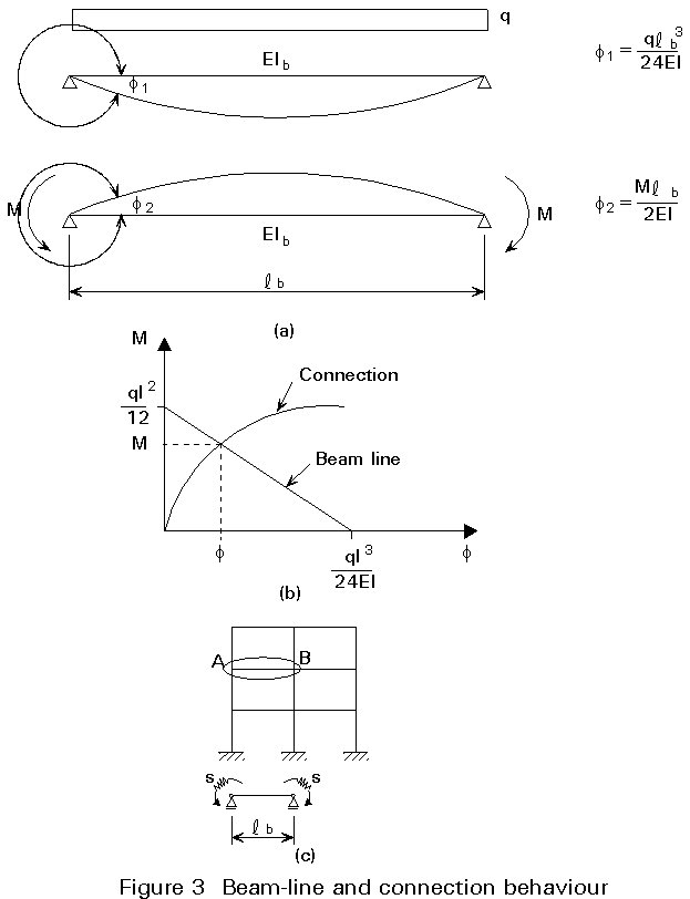
A similar discussion follows for the beam at the roof, see Figure 4. The beam in the first variant has dimensions based on 1/12.q.l2. The moment in the beam can be reduced to 1/16.q.l2 = 1/16.9,1.122 = 82 kNm. The section suitable for that moment is an IPE 270 (Mpl.Rd = 104 kNm). The moments in the connections have to satisfy:
MRd.outer column = (2.1/8.q.l2 - 3.Mpl.Rd.beam) = 327-3.104 = 18 kNm (4)
The connections in the frame have to fulfil requirements for strength, stiffness and rotational capacity. The mechanical properties of connections can be determined with the help of Annex J of Eurocode 3 [1]. This procedure consists of numeral checks. To complete the design process, the connections are designed with the help of CASTA/Connections, a computer program for the determination of mechanical properties of bolted end plate connections according Annex J.
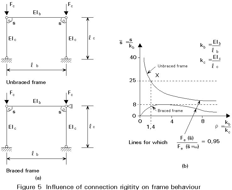
First the double symmetrical connections at the inner column on the floor level are designed. From the frame analysis it has become clear that there is a need for a high resistance in these connections. The web of the column is a relative weak part of the connection. Therefore a web panel and a haunch are included in the design. The mechanical properties of a connection as shown in Figure 5 are as follows:
MRd.inner column = 200 kNm;
Cv.inner column = 64000 kNm/rad
Rotational capacity: sufficient
The other two types of end plate connection are shown in Figures 6 and 7 and have the following resistances:
MRd.outer column T = 118 kNm;
Cv.outer column T = 28000 kNm/rad
Rotational capacity: sufficient
MRd.outer column knee = 26 kNm;
Cv.outer column knee = 1400 kNm/rad
Rotational capacity: sufficient
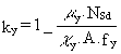
The columns are designed for flexural buckling about the minor axis. Flexural buckling about the major axis has still to be checked, because the moment in the connections forces the column to behave like a beam-column. This check can be done with the help of Eurocode 3 Clause 5.5.4(1) [1]:
![]() (5)
(5)
where
 but ky £ 1,5
 but m y £ 0,90
c
min is the lesser of c y and c zc
y and c z are the reduction factors for the yy and zz axis respectivelyb
My is the equivalent uniform moment factor of the yy axis which represents the moment distribution over the length of the columnWpl.y and Wel.y are the plastic and elastic section moduli
A number of parameters in this formula still have to be determined.
The check will be carried out with conservative values for the different parameters. If the result of the calculation doesn't satisfy the requirements, more sophisticated methods can be used for the stability check.
The columns between the base and the first floor are exposed to the greatest risk of flexural buckling, so these columns have to be checked.
The connections appear to be rather flexible compared to the beams. The distribution of forces between the inner and outer column for a floor can be based approximately on the ratio between the stiffnesses in the two connections. This basis leads to the following results:
MRd. outer column = ![]() (6)
(6)
MRd. inner column = ![]() (7)
(7)
The inner column has to be checked for "chess-board loading", in which one field is loaded by dead load only and the other with imposed load. The normal forces in the inner column are then:
NSd. outer column = 372 kN
NSd. inner column = 772 - 12.13,6 = 690 kN
A conservative approximation for the moment distribution in the column is as follows:
MSd. outer column = MRd. outer column = 78/n = 39 kNm (8)
MSd. inner column = MRd. inner column = 176/(n.(q1 /qr))= 44 kNm (9)
where:
n = 2, depends on the fact that connection moment will be distributed between two parts of the column: the part above the first floor and the part below the first floor
q1 /qr = (![]() = 2,0. It is the ratio between the equally distributed load left and right from the column, due to the "chessboard" load case)
= 2,0. It is the ratio between the equally distributed load left and right from the column, due to the "chessboard" load case)
The buckling resistances according Eurocode 3, Clause 5.5.4(1):
m
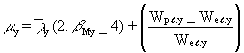
y. outer column = y (2.b My - 4) + (10)
(10)
= 0,71 (2 . 1,8 - 4) + 0,15 = -0,13
m
y. inner column = y (2.b My - 4) + (11)
= 0,58 (2 . 1,8 - 4) + 0,15 = -0,08
ky. outer column =  (12)
(12)
= ![]()
ky. inner column =  (13)
(13)
= ![]()
My.Sd. outer column = 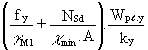 (14)
(14)
= ![]()
= 14 kNm
£ 39 kNm: so not OKMy.Sd. inner column = (14)
= ![]()
= 21 kNm
£ 44 kNm: so not OKFor this specific case the stability against flexural buckling about the major axis does not satisfy Eurocode 3 [1]. An inner column HE240 A and an outer column HE200 A has to be used.
However, the stability of columns between the other floors is no problem.
The costs of this variant have not been calculated, because it can be expected that the larger column dimensions and the effort which has to put in the moment connection is not the most beneficial.
A variant exists which is almost the same as the last variant, but the floor beams are replaced by IPE 500 and the column sizes are HE180A for the outer columns and HE220A for the inner columns. The moment resistance of the floor beam is 470 kNm. The following equation holds for the resistance in the connections:
MRd. outer column + MRd. inner column = 2.(1/8.q.12 - Mpl.Rd.beam)
= 41 kNm (16)
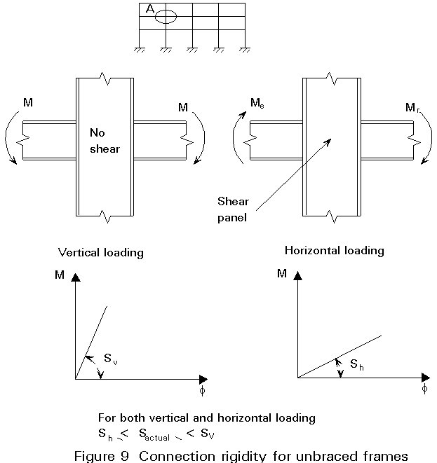
It appears that the connections are rather flexible compared with the beams (Figures 8 and 9).
MRd. inner column = 90 kNm;
Cv. inner column = 5600 kNm/rad
Rotation capacity: Sufficient
MRd. outer column T = 60 kNm;
Cv. outer column T = 1200 kNm/rad
Rotation capacity: Sufficient
The distribution of forces between the inner and outer column for a floor can be based approximately on the ratio between the stiffnesses in the two connections. This basis leads to the following results:
MRd. outer column = ![]() (17)
(17)
MRd. inner column = ![]() (18)
(18)
A conservative approximation in this case for the moment distribution in the column is as follows:
MSd. outer column = MRd. outer column = 7/2 = 4 kNm (19)
MSd. inner column = MRd. inner column = 34/(2.2,0) = 9 kNm (20)
The buckling resistances according Eurocode 3, Clause 5.5.4(1):
My.Sd. outer column = 14 kNm
³ 4 kNm: so OK (21)My.Sd. inner column = 21 kNm
³ 9 kNm: so OK (22)For this specific case the stability against flexural buckling about the major axis satisfies Eurocode 3 [1].
The stability of columns between the other floors is no problem.
Application of an IPE 500 can lead to very simple moment connections such as short end plate connections. The stability of the inner columns HE220A and the outer columns HE180A is hardly affected by the moments from the connections onto the columns, so flexural stability about the major axis is no problem. The simple end plate connections are shown in Figures 8 and 9.
The vertical deformation of this variant is no problem.
The costs of this alternative as calculated with the help of TVC are shown in Table 2 Variant 3.
It is possible to design the portal frame with full-strength and rigid connections. In general, this design leads to beams of less weight. In the example the following is the result:
MRd. outer column = (2.1/8.q.12 - 3.Mpl.beam) = 980 - 3,278
= 147 kNm (23)
The outer column must be able to carry this load from the connection, so the moment resistance of the outer column section is 147/2 = 74 kNm. Therefore, a HE200A (Mpl.column = 92 kNm) is necessary. Flexural buckling about the major axis has to be checked as well.
The conclusion is that full-strength and rigid connections do not lead to an economical design of the frame and connections. Use of small beams leads to heavy columns and extensive reinforcement of connections. It can be worth investigating a full- strength and rigid connection design only if the height of the structure has to be a minimum.
When designing connections in a framework, it can be useful to consider semi-rigid and partial strength connections. In the example given it appears that full-strength and rigid connections are not economical. Semi-rigid and partial strength connections can lead to saving of cost (in the example the saving is 13% based on Dutch prices) and reduction of the structural height when compared with a design using nominally pinned connections.
[1] Eurocode 3: "Design of Steel Structures": ENV 1993-1-1: Part 1.1: General Rules and Rules for Buildings. Annex J: Beam-to-Column Connections, CEN, 1992.