ESDEP WG 14
STRUCTURAL SYSTEMS: BUILDINGS
To present the basic principles of design and analysis of a single storey building with trusses and stanchions. To illustrate with a design example.
Lecture 2.3: Engineering Properties of Metals
Lecture 2.4: Steel Grades and Qualities
Lecture 3.1: General Fabrication of Steel Structures
Lectures 6: Applied Stability
Lectures 7: Elements
Lectures 11.4: Analysis of Connections
Lecture 11.5: Simple Connections for Buildings
Lectures 14.1: Anatomy and Analysis of Single Storey Buildings
The many factors which can influence the conceptual design and detail design of trussed framework construction for single storey buildings are introduced.
Design criteria relating to layout, spacing, cladding, connections, services, movement, fabrication, transportation, erection, foundations, and environmental effects are discussed.
Methods of analysis for latticed roof trusses are described and load paths, bracing, and pinned/rigid joint nodes are discussed.
The brief for the design of the majority of single storey industrial buildings is essentially to provide a structure which is without, or has a limited number of, internal columns. In principle the requirement is for the construction of four walls and a roof for a single or multi-bay structure. The walls can be formed of steel columns with cladding which may be of profiled or plain sheet, precast concrete, or masonry. The designer considers a system of beams or frameworks (latticed or traditional) in structural steel to support the cladding for the roof. Use is made of hot rolled hollow sections (circular, rectangular) and traditional sections (I sections, angles, etc.) and also cold formed sections.
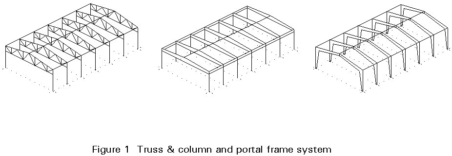
Light latticed frameworks for the roof of an industrial building provide a neat, efficient, structure which is simple to design, economic to execute and frequently satisfies architectural requirements. Whilst the structural envelope and the design are `basically' simple, it is essential to ascertain correctly the loads applied to the structure and to predict the load paths from the sheeting to the purlin and side rails, through the roof girder to the column and finally to the foundation and supporting soil. Various building forms are described in Lectures14.1 and 14.5. A typical truss and stanchion frame is shown in Figure 1.
Following the decision to use a steel structure for an industrial building, the aspects described below are considered by the designer. The aim is to meet the requirements of the client and enable a cost-efficient solution in relation to fabrication, transportation and erection.
The overall dimensions of the building (length, width, height) are based on the information from the client concerning the intended use of the building, the site on which the structure will be built and the relevant regulations.
The inclination of the roof is usually selected to be as low as possible in order to reduce the roof space to the minimum and consequently the running costs of heating and ventilation. The most economical form of roof construction is probably one of low pitch, between 1° and 6° , which uses a simple form of cladding and which minimises deflection so that no weather protection is needed, whilst maintaining reasonable heating costs.
The principal structural components of an industrial building are the cladding and purlins, the lattice girders and the columns. They should be arranged to meet all serviceability requirements and safely transmit all relevant vertical and horizontal loads to the ground.
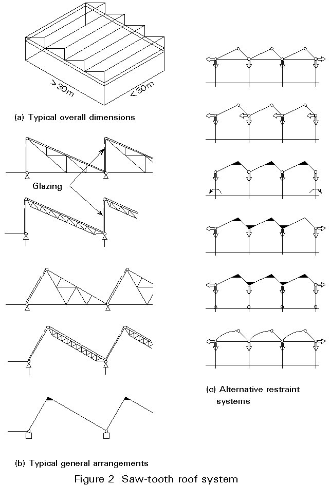
Cladding and wall elements are usually sandwich panels consisting of two trapezoidal sheets with insulation between them (Figure 2a). In the few cases where heating protection is not required, simple trapezoidal sheets may be used. The sheets are cold formed with thicknesses between 0,75 and 2,0 mm. They are generally galvanised against corrosion. The cladding panels are connected to each other by overlapping and special screws, which are also used for the connections to the purlins. More information is given in Lecture9.4. Cold formed galvanised Z or C sections are usually used for purlins, although IPE sections may also be used (Figure 3a). The cold-formed sections are easily connected together by overlapping and the use of special screws. Z sections have the additional advantage that their principal axes of inertia may be selected to be vertical and horizontal, so that no transverse bending is produced by the vertical loads due to self weight or snow. In the presence of large transverse bending, anti-sag bars may be added between the purlin supports (usually 1 or 2) to increase their lateral stiffness (Figure 3b). However the bars can increase labour costs and their use should be weighed against lateral purlins or closer frame centres.
Purlin distances range between 1,8 m to 2,0 m to suit the cladding dimensions. If they are located between the nodes of the lattice girders, bending and shear is induced in the top boom member in addition to axial forces.
Lattice girders are used in cases where the spans become so large (usually greater than 30 m) that standard I sections may not be used. Since they have a much larger second moment of area and section modulus than a corresponding I section of a similar weight, they have greater stiffness and resistance to load. These enhanced properties are however accompanied by higher fabrication and erection costs due to the required effort for the connections. For this reason some contractors prefer to use welded I girders of variable height and slender webs. Spans up to 80 m have been realised in that way.
Different layouts of the internal member of a lattice roof girder are possible, Figure4. Since the diagonals are likely to be subject to stress reversal due to wind effects, the warren type truss is generally preferred.
Frames are normally positioned at 6,0 m to 7,5 m centres. These spacings generally provide economic solutions for the cold-formed purlin and side rail arrangements.
Generally a decision is taken early during the process of conceptual design on the type(s) of member(s) to be used for the latticed frame. There are many alternatives:
a. Hollow sections - circular or rectangular.
b. Traditional sections - angles, tees, channels, I sections.
c. Combination of (a) and (b).
The selected truss should reflect not only the design aim to produce the lightest frame but also fabrication and erection requirements.
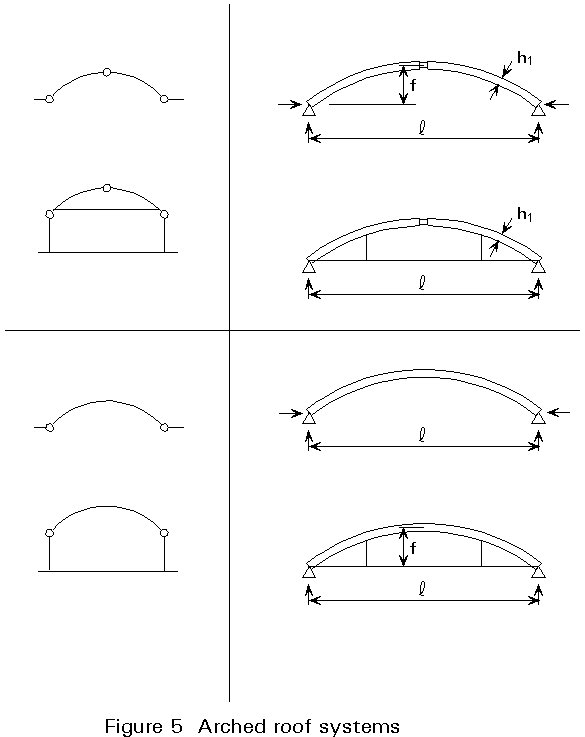
An example of composite form is shown in Figure 5 where the booms are I sections and the internal members are RHS. The I sections enable easy connection of services to the truss and easy connection to columns. Bracing in the plane of the roof can be provided using simple in-plane members and simple connections, or by using the relative stiffness of an I or H section.
The specific advantages of hollow sections (and tubes) when compared with traditional sections (I sections, channels, angles, etc.) are the high strength to weight ratio, maximum efficiency in tension, efficiency as struts, good torsional properties, appearance and maintenance. In considering use of CHS or RHS the designer should remember that some fabricators are not fully equipped to fabricate circular hollow sections. The main disadvantages of CHS and RHS are the higher cost of connections at some nodes, the relative difficulties of making on-site connections for services (electrical, etc.). In addition basic costs are higher than traditional sections on a tonnage basis (overall however frames of lighter weight are produced).
The relative slopes of the internal members should be considered in relation to the detailing and fabrication process. If they are parallel to each other then the angle of cut at each end is identical for all members.
The final decision on the type(s) of member(s) to be used may be influenced by aesthetics and not cost.
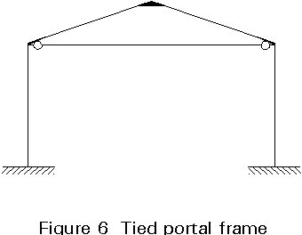
Generally, the columns to the frame are I or H sections (Figure 6a). The latter have a greater transverse stiffness than the former and are preferred in cases of biaxial bending. When the building incorporates an overhead travelling crane of high capacity, a built-up load or battened column may be used (Figure6b). In some cases the built-up columns are continued by I sections over the level of the crane supporting structure in order to reduce the costs, (Figure6c).
Bracing, both horizontal and vertical, must be provided to accommodate horizontal loads due to wind and possibly earthquake. It is possible to use the cladding and wall panels instead of braces for this purpose. In that case stressed skin design should be used (Lecture 9.5).
When masonry is used as all or part of the vertical cladding, it is feasible to use that element as part of the bracing system.
The bracing can be single diagonals or cross members. If the former system is adopted, the members are designed to support compressive and tensile loads. When cross members are used only the members in tension are assumed to be effective, those in compression being designed to satisfy the slenderness criteria.
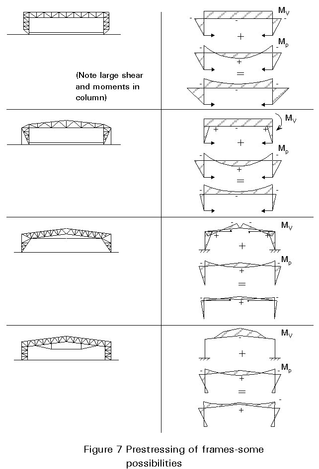
Bracing in the roof may be located either at mid-length of the building (Figures7 and 8a) or at its ends (Figures 7, and 8b). The latter has the advantage that horizontal loads are directly transmitted to the ground. This arrangement is also helpful for erection purposes, since it provides a stable structure at one end of the building when the execution starts. Its disadvantage is that it prohibits the free movement of the building due to temperature so that stresses in the members, sometimes of considerable amount, may result. By putting the braces at the mid-length this disadvantage disappears since the building is able to expand freely. However additional temporary braces should be provided during the erection stage to stabilise the first part of the building. The horizontal forces have to "travel" from their point of application in the gable to the brace thus causing compression in the purlins.
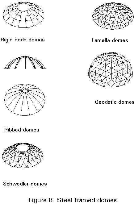
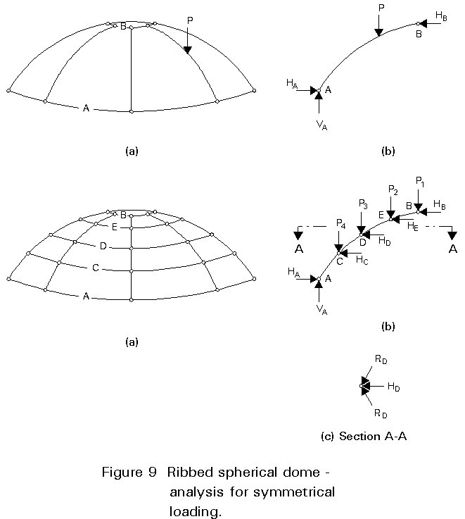
The longitudinal stability of the structure may be assured also by frames (Figure8c), or by rigidly connecting the columns to the ground where the building has to be free from braces. The transverse stability is provided by some form of frame structure (Figure 9). For cases where the truss is rigidly connected to the column (Figures 8a, b and 6a), the high shear that is developed at the top of the column must be accommodated.
The following loadings are considered in the analysis of industrial building structures:
- structural elements.
- cladding.
- services.
The design of the structure is usually performed in two stages as follows:
Preliminary Design
a. Select girder depth, d, between span/20 and span/30.
b. Decide on span of sheeting, i.e. purlin centres and frame layout (e.g. warren truss, etc.).
c. Evaluate dead, imposed and wind loads, assuming self weight is 50% of weight of cladding.
d. Assuming total roof loads are uniformly distributed, evaluate:
i. Bending moment in the girder, using M = WL/16 where W is the factored dead and imposed loads. Hence find force in the top and bottom boom, equals M/d.
ii. Shear in end panel, equals W/2, hence find forces in internal members.
iii. Second moment of area of girder to satisfy deflection, using deflection < L/200, hence I > 0,5 WL2 cm4, where W is the unfactored imposed load.
e. Select initial sizes of members assuming stresses in booms are 250 N/mm2 (Grade 43 steel), in diagonal struts 220 N/mm2, in diagonal ties 275 N/mm2, and to satisfy I = 0,5 WL2 where I = Ad2/2 and A is the area of the top boom.
f. Check self weight and adjust as necessary.
g. Select column section, assuming Icolumn = Iboom/3.
Final Design
a. Model the structure as close as possible to the actual conditions (joints, supports, etc.).
b. Using computer analysis evaluate forces due to all loading.
c. Design girder and column members to appropriate code(s).
d. Check self weight, adjust calculations as necessary.
e. Design bracing systems.
f. Design connections, including base.
Important factors which must be considered at the conceptual and detailing stages are the questions of workshop facilities and space and of transport between workshop and site. Whilst large girders and/or large sections may appear to be desirable in order to reduce the number of site connections, the use of large members can often reduce the number of fabricators who can tender for a given project.
The lengths of members available from stockists or direct from the mill can vary. When long lengths are deemed desirable it is necessary to check their availability. Generally standard sections can be obtained in a reasonable time but there is likely to be delay and possibly additional cost if non-standard sections are required. The use of slightly heavier sections and standardisation of section size may lead to a cheaper fabricated structure. This however may result in more expensive supporting structures (due to increased dead weight), including foundations. When large prefabricated trusses are used it is necessary to provide lifting points (eyes) which are located to minimise stresses induced during lifting. All parts which are shop painted need to be handled carefully to avoid damaging the coating.
Latticed girders are made up of long, basically slender members, and may therefore be subject to severe distortion due to welding unless care is taken during the fabrication process.
It is essential that the design engineer notes that:
i. bulk orders of minimum size variation are cheaper than small orders of many different sizes.
ii. the number of pieces to be handled should be kept to a minimum.
iii. weld distortion and tolerances should be allowed for.
iv. automated fabrication is generally cheaper.
v. careful design can minimise transportation costs.
vi. specifications need to be realistic to reduce costs.
vii. good quality control is essential.
In each country there are specific lengths and widths of structures that may be transported without any problems, e.g. widths up to approximately 3 m, lengths up to 15m. For larger dimensions a police notification or special permission is required.
It should be noted that the various police authorities specify different periods when abnormal loads are allowed to move through their districts. If neighbouring "times" are significantly out of phase and general traffic hold-ups cause disruption to the movement of abnormal loads, it is possible for loads to be delayed by up to 24 hours. If one or more cranes and associated erection staff are unable to work because of these enforced delays, the additional costs can be very significant. Some towns and cities place length restrictions on materials which can be moved by road.
Girders can be fabricated and despatched lying flat. The overall height allowed for the load is dependent upon the route travelled and the clear height of any bridges likely to be encountered. Rail transport can accommodate long pieces, but width and height are more restricted.
To limit the length of units being transported, trusses may be divided into welded parts (2, 3 or more parts) which may be bolted together on site. The complete rafter can be then craned into position.
For export where shipment is involved, pieces up to the same dimensions as for road transport may be accommodated. It should be appreciated, however, that shipping charges are often based on volume rather than weight. There are often relatively severe restrictions on the length of a piece that can be carried in the hold of a ship. The ship's engineer may refuse to carry steelwork as deck cargo. It may be found more economical to despatch the steel in pieces for subsequent assembly on site.
In considering the erection of a framework, the designer seeks an economic but safe process. The cost of erection can be a significant proportion of the cost of a steelwork contract. It is often useful for a designer with little or no experience of steel erection to discuss possible solutions with a contractor. The latter will know how to build and avoid the possibility of collapse and how to satisfy the insurer. Potentially steelwork erection is hazardous and good control is required to ensure safety of the erectors.
Latticed girders can conveniently be assembled on the ground and lifted into place. However, since cranes are likely to be used, the effect of dynamic lifting loads or stress reversals should not be ignored. All steel structures are likely to require temporary bracing, which may be part of the permanent system. The temporary systems need to be carefully designed. The following points summarise the process:
a. Structural steelwork erection is an operation requiring meticulous planning from conception to completion.
b. The operation involves many disciplines and requires co-operation and communication between all those involved.
c. It is an operation which is dependent upon the personal competencies of all those involved to ensure the contract is completed without accident, on time and within the budget.
a. This lecture outlines latticed truss and stanchion design. It concentrated initially on important aspects which must be considered during the conceptual design and the detail design stages.
b. Careful initial dimensioning is necessary to produce an economic solution, to avoid secondary stress effects in the rafter where possible, and to obtain a design which can be fabricated, transported and erected with minimum problems.
c. Elastic analysis is used and using the assumption of the truss joints as pinned simplifies the design process.
d. It is useful to develop methods for preliminary sizing of members. Some proven methods are available.
e. Care must be taken in:
i. the provision of lateral bracing to the rafter and to the column.
ii. joint design.
LECTURES
Lecture 9.4: Page 4
Lecture 9.5: Page 6
Lecture 14.1: Page 3
Lecture 14.5: Page 3