ESDEP WG 12
FATIGUE
Introduction to design concepts in the presence of structural damage, and to life prediction methodologies.
None
Lecture 12.7: Reliability Analysis and Safety Factors Applied to Fatigue
Lecture 12.10: Basics of Fracture Mechanics
Lecture 12.12: Determination of Stress Intensity Factors
The basic concepts of safety, durability and reliability are briefly introduced and discussed with reference to structural engineering applications. The basic principles for fail-safe and safe-life design are presented. The main parameters to be accounted for in a fatigue life prediction are briefly presented and discussed.
If a structural member or connection is subjected to a cyclically varying load, it may fail after a certain number of load applications even if the maximum nominal stress in a single cycle is much less than the yield stress of either the material or the weld metal or the fastener.
A crack may in fact be initiated at some mechanical or metallurgical discontinuity (stress concentration) and be propagated through the material with successive load repetitions until the affected part loses its ability to carry the load. This failure mechanism is known as "fatigue".
Many failures of engineering structures are attributed to the consequences of pre-existing cracks or crack-like discontinuities. Unfortunately, standard design models for beams, columns and trusses which use conventional stress analyses and strength of materials methods, cannot evaluate the effects of cracks in structural elements. Fracture mechanics principles enable a more rational assessment of structures containing cracks to be carried out.
Originally, most structural engineering applications of fracture mechanics were limited to in-service assessment of structures, mainly aircraft. Recently, the size and shape of discontinuities have been correlated to fabrication quality levels [1]. As a result, code-drafting committees are beginning to employ fracture mechanics calculations in order to evaluate specifications for quality assurance. Furthermore, when no specifications are applicable, fracture mechanics can be used directly by the engineer for evaluating non-destructive inspection results.
The concept of damage-tolerant design is perhaps the major justification for the use of fracture mechanics. This concept accepts the possibility that an element remains useful when it has been subject to damage upon fabrication, transportation or even after several years in service. Such damage, is often manifested by cracking.
Damage tolerance has now become a standard design concept in some engineering fields; acceptance of certain aspects is apparent in structural engineering, where new concepts are becoming more and more common.
Of particular importance, when adopting a damage-tolerant-design approach are the concepts of safety and durability.
Both safety and durability requirements can be satisfied by considering initial damage in the structure (or in the structural element) and assuring that such damage does not grow and reach specific limits in prescribed time intervals.
Safety is associated with the extreme (i.e. the worst case) damage that may be missed during manufacturing inspection. This damage must not grow and degrade the strength of the structure (or of the member) below specified limits throughout the service life. Durability limits are associated with the economics of in-service repair, i.e. initial damage typical of common manufacturing procedures is not allowed to grow to a size sufficient to require extensive rework or repair in less than one design service lifetime.
Current practice involves the use of deterministic methods and fracture mechanics concepts to predict the accumulation of crack growth damage. Engineering experience with the use of these methods has allowed the proper emphasis to be placed on design decisions affecting such factors as allowable stress. Most of the input data for the deterministic methods are available in statistical format (e.g. initial flaw sizes, material properties...) and thus it is possible to make estimates of the probability of damage growth exceeding a specified level. Both the deterministic and probabilistic approaches require a model of the damage accumulation process. Lack of essential data for important variables and inexperience of the use of fracture mechanics and reliability methods for making conventional design decisions have been the main reasons for these techniques not being used in current practice.
When dealing with structural damage, two major concepts must be taken into consideration: damage growth and damage containment. These concepts give the two criteria for:
a) Safety - the assurance that safety (that is the strength) of the structure will achieve and maintain a specified residual level (in the presence of undetected damage) through the anticipated service life.
b) Durability - the assurance that the structure can operate effectively with a minimum of structural maintenance, inspection, costly retrofit, repair and replacement of major parts due to the degrading influence of general cracking, corrosion, wear, etc.
Safety and durability limits are specified, designs chosen to comply, tests conducted to verify and management procedures established to maintain and/or adjust the limits in service. Each structure must meet both the safety and durability requirements.
Past experience with testing of structural members under simulated service loading conditions indicated that time to initiation of cracks from most structural details, such as sharp corners or holes, is relatively short and that the majority of the life (i.e. as much as 95%) is spent growing the resultant cracks to failure [2]. Likewise, analyses of in-service fracture, cracking instances, etc. have indicated that a major source of cracks is the occurrence of initial manufacturing defects such as sharp corners, tool marks, weld inclusions and the like [3]. Thus it is now common practice to consider the damage accumulation process as entirely crack growth with zero time to initiate the crack. Although this assumption may seem unduly severe, the consideration of initial damage in the form of cracks or equivalent damage is absolutely necessary to ensure structural safety.
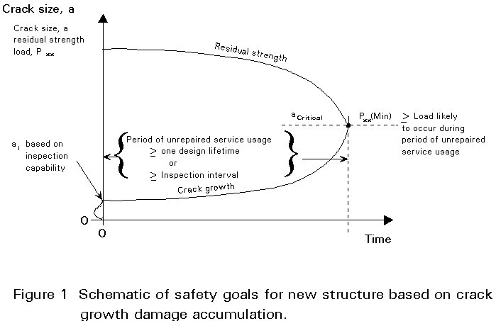
Figure 1 (from [4]) includes a schematic of the damage model associated with structural safety.
Safety is ensured by designing to specific requirements of damage tolerance in which initial damage is never allowed to grow and reduce the residual static strength of the structure below a prescribed level, Pxx, throughout the life of the structure (or of the structural element). As indicated in Figure 1, Pxx is the greater of the design limit load or the maximum load that might be encountered during the specified minimum period of unrepaired service usage. If in-service inspections are required to ensure safety (e.g. for fail-safe designs) then the residual strength level, Pxx, is the maximum load likely to occur during the inspection lifetime. The assumed initial damage, ai, is that associated with the capability of manufacturing inspection.
When the concept of structural durability is considered, it includes "fatigue" procedures. In addition it includes also the requirements for protection against such degrading factors as corrosion, stress corrosion, wear, fretting, etc.
To prevent widespread cracking, a flow growth model can be considered such as that shown in Figure 2 (from [4]).
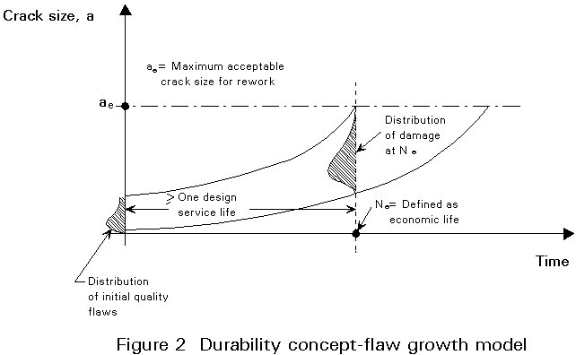
In Figure 2 the limit, ae, is not failure as in the safety requirement but is associated with a size of crack that can be repaired. The economic life, Ne, is defined as that time when the population of such cracks in each structure (or structural element) just reaches sufficient size that rework or repair is no longer cost-effective. The durability specification requires that the "economic life" be in excess of the design service life. In the example shown in Figure 2, the initial population of flaws represents "apparent initial quality", or the conditions of structural details following typical manufacturing operations such as hole drilling, shop or field welding, etc.
Since the limit for economic rework is strictly related to the manufacturing procedures (for example, for fastener holes, it is of the order of the next minimal hole size), it is clear that the limit of growth for durability requirements is significantly smaller than for safety.
Durability is associated with total flaw population, or total number of flaws in excess of the economic rework limit for each member (or joint) in the structure. Safety is concerned with the "worst case" of flaw size likely to be missed during an inspection.
In general it is not possible to anticipate the extent of usage of a structure (or structural detail). Design is accomplished with the best estimate of typical usage and variance in expected usage. Thus safety and durability limits of some individual structural detail may be shorter than estimated in design. This condition places a tremendous emphasis on life management and in-service inspection of individual structures. In practice, design estimates of safety and durability limits, as well as of remaining fatigue life, are adjusted to reflect usage severity based on analyses of the accumulation of crack growth damage performed on individual structures.
In the design of a structure which is to be subjected only to static loading, the design process consists essentially of choosing the structural dimensions so as to satisfy at all points the condition:
![]() (1)
(1)
where the function of the cross-section size may be represented by an area, a section modulus, etc., corresponding to functions of the applied loading such as axial load, bending moment, etc., and the design stress is exclusively a function of the mechanical property of the material, such as yield strength or ultimate tensile strength. Equation (1) is quite independent of the detailed shape of the structure at any particular point, and its solution requires only the application of simple mathematics.
The design of a structure which may suffer fatigue failures is, on the contrary, a somewhat more complex process. In fact the fatigue strength depends on many more variables than the static strength of the material, and particularly on the detailed design of the joints in the structure. Thus, although the equation which has to be satisfied is still the same, there is the additional problem of selecting a suitable value for the design stress. This selection becomes the main issue when designing a structure against fatigue.
The first difficulty is to decide what one is trying to achieve in terms of life, i.e. how long should the structure last. In the past, even though detailed design to prevent fatigue damage was not common, infinite life was often achieved (it is sufficient to think as an example of Roman bridges, some of which are still standing at present because the static design of structures involved the application of large safety factors and the use of approximate design methods, which resulted both in the use of pessimistic estimates of design resistance and in the overestimation of the service loads.
However, design stresses have steadily increased and the use of more sophisticated design methods means that, nowadays, design stresses tend actually to be present in structures in service. This level of stressing is the reason why fatigue has become a problem. The only way that a designer can ensure infinite life is to use working stresses below the fatigue limit of the joints in the structure. This approach implies the use of very low working stresses. However, if any stress cycle has an amplitude greater than the fatigue limit, then it must be accepted that failure will eventually occur and the life be finite.
The designer is therefore in a dilemma. Is he to keep the stresses very low, inevitably at the expense of a heavy structure, and try to obtain infinite life, or is he to accept a finite life? And if he does accept a finite life, on what basis is he then to choose the design stresses?
Much of the thinking on this subject has originated in the aircraft industry (where weight saving is of particular importance). It is of particular interest to consider the two design philosophies which were developed by aircraft engineers, which are known as the "safe-life" and the "fail-safe" concepts of structural design.
In the "safe-life" method the designer starts by making an estimate of the load spectrum to which the critical structural components are likely to be subjected in service. These components are then analysed or tested under that load spectrum, so as to obtain its expected life. Finally a factor of safety is applied so as to give a safe life during which the possibility of fatigue failure is considered to be sufficiently remote. At the end of that period, the structural components concerned are automatically replaced. It is important to realize that, even though the estimate of the laboratory life can be made by practical tests, the safe-life method is ultimately theoretical in nature. The critical step is to derive from the expected life the safe life. The factor of safety introduced at this stage has to allow for a large number of unknowns, such as scatter obtained in fatigue test results, errors in the estimate of the load spectrum and the effect of extraneous variables such as environmental conditions, corrosion, etc. It is clear that by making the factor of safety sufficiently large, the designer can govern the probability of failure associated with his design. On the other hand, if a fatigue crack does occur, it may well be catastrophic, and safety depends on achieving a specified life without a fatigue crack developing. With this design method, the emphasis is on prevention of crack initiation.
With the "fail-safe" concept the basis of design is that, even if failure of part of the main structure does occur, there will always be sufficient strength and stiffness in the remaining part to enable the structure to be used safely until the crack is discovered. This concept implies that periodic in-service inspection is a necessity, and that the methods used must be such as to ensure that cracked members will be discovered, so that repairs or replacements can be made.
It is clear that with this method of design the probability of partial failure is much greater than with the "safe-life" design. In developing a fail-safe structure, the safe-life should also be evaluated, in order to make sure that it is of the right order of magnitude. However, the emphasis, instead of being on the prevention of crack initiation, is on producing a structure in which a crack will propagate slowly, and which is capable of supporting the full design load after partial failure. The basic principle of fail-safe design is therefore to produce a multiple load-path structure, and preferably a structure containing crack arresters. In addition, the structural elements must be arranged so as to make inspection as easy as possible. In areas where that is not possible, the elements must be oversized so that either fatigue cracking does not occur in them, or fatigue crack growth is so slow that there is no risk of failure.
It must be emphasized that the objective of both philosophies is the same, namely to reduce to a negligible level the risk of catastrophic failure. It is now generally accepted that neither method is satisfactory when applied in isolation [5]. Both are necessary and they are not mutually exclusive. In fact, a safe-life design would produce a structure with a high level of freedom from fatigue cracking; however, the same structure should possess fail-safe characteristics.
As a consequence, even in as critical and expensive a structure as an aircraft, designers are prepared to accept a philosophy which results not only in a finite life from the point of view of fatigue cracking, but also, with sufficient safeguards, in a structure which may contain fatigue cracks during part of its working life.
Once the idea is accepted that it is reasonable to design a structure on a finite life basis, it is clear that the exact design philosophy to be adopted depends on the consequences of failure. Sometimes, a satisfactory design method is provided by a modified safe-life philosophy, the so called "working-life" method [5].
The objective is not to reduce the risk of catastrophic failure to a negligible level, but to produce a structure which will usually (but not necessarily always) be free from fatigue cracks for a specified life. As compared with the true "safe-life" philosophy, less importance is placed on making an accurate estimate of the safe life. In formal terms, this means that two important changes are made in that philosophy: (a) that the structure is not automatically replaced at the end of its "safe working life", and (b) that it is accepted that some cracking may develop before the "safe life" is reached. It therefore becomes reasonable, instead of estimating the safe life accurately by carrying out programmed fatigue tests on specimens representing the particular structure, to estimate it analytically by using fatigue test results obtained on laboratory specimens representing standard details typical of those used in the structure.
It is important to notice that each of the previously described methodologies essentially imply a different probability of failure. In fact, for a safe-life design, it might be decided to use an S-N curve relating to the mean minus 2 standard deviations of Log N (corresponding to the 97,7% probability of survival), while for fail-safe design the S-N curve corresponding to the mean minus 1 standard deviation (representing the 84,1% probability of survival) might be considered to be sufficiently conservative.
In current practice, designs are chosen to satisfy specific safety and durability life and strength requirements by deterministic analyses of damage growth and residual strength. Decisions on materials, structural configurations, allowable stresses, etc., are based upon the results of these analyses.
Durability of metallic structures is influenced by the local details of joints, splices, welds, fasteners, eccentricities, etc. For a given design, the lower the gross stress, the more durable the design.
Analyses of crack growth damage, while generally deterministic, rely on input data such as initial flaw sizes, material and usage variability, etc., which are available in a statistical format. Thus, in addition to predicting mean values of damage accumulation, the methods can be used to predict the distribution of damage with time. For example, under specific usage and assumed distributions of the other variables, it is possible to estimate the distribution of lives, growth rates, final flaw sizes, etc. and thus the probability of equalling or exceeding a certain requirement. If only one variable is considered, the estimation can be straightforward. When joint probabilities are involved, the procedures become more complex. The results of the probabilistic analyses are extremely sensitive to the initial distributions of the variables and the functions used to approximate them. Among the major variables to be considered are:
Although published reliability methods can be found in the literature, current practice does not in general reflect their use. In fact, the sparsity of data associated with the major variables listed above, and the extreme sensitivity of the results to the distribution functions has limited the effectiveness of, and the confidence in, the results. Furthermore, the design to a specified reliability level requires that the acceptable failure rate be established in advance, and that relationships be established between reliability and normal design decision factors (i.e. allowable stress, structural configuration, etc.). Since overall structural reliability can be significantly altered by factors other than those normally considered in design (e.g. inspection frequency), it is rather difficult to assign the proper weighting function to any particular variable.
Actually, reliability techniques have been more successful in assessing older structures (i.e. in assessing remaining fatigue life) where extensive test and service failure data are available to establish the mean time to failure with some degree of confidence [6].
For the concept of durability described in the previous paragraphs, probabilistic techniques may have the most direct impact, since the ultimate decision on the economic life is connected to the global population of cracks just below the rework limit. Safety requirements, on the other hand, account for growth of the extremes of the initial flaw population and other variables (i.e. the worst case). It is anticipated that the requirements will continue to be satisfied with conventional practices based on deterministic methods.
In summary, methods for calculating the accumulation of crack growth damage are required for both deterministic and probabilistic analyses. Lack of essential data for important variables and inexperience with the use of reliability methods for making conventional design decisions have been the main reasons for the nearly complete absence of these techniques in current design practice.
Currently, life prediction for a structure subject to variable loading is generally based on crack growth damage integration models which use a data base and analysis to interrelate the following elements:
(a) initial flaw size and distribution
(b) loading conditions
(c) basic crack growth material properties
(d) crack and structural properties
(e) damage model
(f) fracture or life limiting criteria.
These models are always calibrated on the basis of test results, and the confidence normally associated with life predictions is usually derived from the ability of the model to predict the laboratory generated crack growth behaviour.
The only quantifiable measure of fatigue damage is a crack. Cracks impair the load-carrying characteristics of a structure. A crack can be characterized for length and configuration using the stress intensity factor K, a structural parameter interrelating the local stresses in the region of the crack tip with (a) crack geometry, (b) structural geometry, and (c) level of load on the structure.
The crack grows in response to the cyclic loading applied to the structure. Any crack (a) will grow a given increment (Da) when subjected to a given number of cycles (DN), the rate being measured by ![]() . When the crack length reaches a critical value (acr), the growth becomes unstable, thereby inducing failure. The life (NF) is the measure of accumulated cycles required to drive the crack from its initial length ai to the critical length acr. The interrelationship between crack length, loading and residual strength of a structure is illustrated in Figure 3 (from [4]).
. When the crack length reaches a critical value (acr), the growth becomes unstable, thereby inducing failure. The life (NF) is the measure of accumulated cycles required to drive the crack from its initial length ai to the critical length acr. The interrelationship between crack length, loading and residual strength of a structure is illustrated in Figure 3 (from [4]).
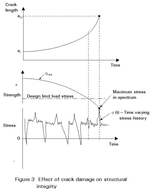
As shown in Figure 3, the monotonic increase in crack length is induced by a continuous sequence of cyclic loads. The residual strength (sres), that is the load carrying capacity of the cracked structure, is shown to monotonically decrease with increasing crack length following an expression of the type:
s
res = Kc/f(a) (2)where:
Kc is a material property, termed fracture toughness, which is a constant for a specific geometry
f(a) = Y(a) ![]() is a structural property (the stress intensity factor).
is a structural property (the stress intensity factor).
When the residual strength decays to the level of the maximum stress in the service load history, fracture occurs. The crack length associated with fracture (i.e. acr) is determined by solving Equation (2) for crack length, assuming that the residual strength equals the maximum stress level in the spectrum, or that it equals the design limit load stress level (whichever is greater). It is interesting to notice that the crack growth rate is directly related to the rate of loss of residual strength through Equation (2), thus justifying the selection of crack length as the main parameter to quantify structural fatigue damage.
A crack of length ai will grow to acr in some service life, NF. Experiments have shown that several parameters affect NF; the most important of these are:
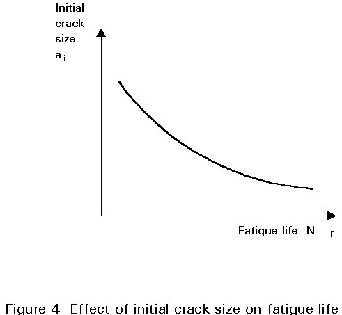
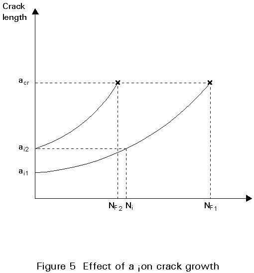
The role of initial crack size on fatigue crack growth is of paramount importance; in fact, as illustrated in Figure 4, given a configuration and loading, the smaller the initial crack size, the longer the fatigue life. Furthermore, the shape of the a-N curve for a given configuration and loading remains essentially constant for any given crack growth increment. Thus, given the crack growth curve from ai1 in Figure 5 (from [4]), it is possible to determine the crack growth curve from ai2>ai1 by simply shifting the previous curve on the left, as shown in the figure, where Ni represents the number of cycles required to grow the crack from ai1 to ai2. It follows that NF2 = NF1 - Ni.
The stress history experienced at each location of the structure will differ due to changes in bending and twisting moments, shear, etc. It follows that similar structural details placed in different locations within the structure will experience different loading histories. Given a particular joint and initial crack configuration, it is clear that, when subjected to a more severe loading spectrum, a shorter life (NF1) will result than under a less severe spectrum (resulting in a longer fatigue life NF2).
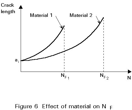
Experimentally, it has been shown that for the same loading condition (i.e. the same number and amplitude of stress cycles) cracks will grow faster in certain materials (or alloys) than in others. The crack growth rate (Da/DN) can be derived experimentally for each material. Given the same load and geometric conditions, the material (or alloy) having the slower growth rate characteristics will have a longer life (NF), as shown in Figure 6 (from [4]).
The most complex of the parameters affecting crack growth behaviour are the structural properties. The structural properties involve such things as crack configuration, load transfer mechanisms, fastener hole size, dimensions and extent of weldments, part thickness, stress concentrations due to geometric effects, etc. A substantial amount of both experimental and numerical work has been performed to characterize the geometrical effects on fatigue life see, for example [2, 3, 5-15].
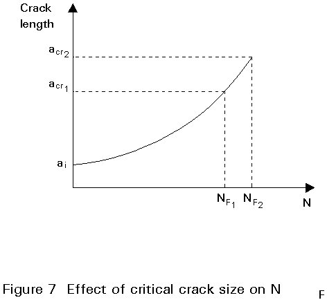
The critical crack length (acr) is a function of material, structural geometry and loading. As shown in Figure 7 (from [4]), for acr/ai sufficiently large (e.g. >5), the relative effect of acr on NF is typically small. The primary advantage of designing for a large critical crack length is the increased inspectability that it provides. A large critical crack length increases the probability of locating the crack before it becomes critical, thereby enhancing structural safety.
Life predictions are usually performed by means of crack growth damage integration models, which interrelate the following elements:
a) the initial flaw distribution, which accounts for size variations and location of cracks in a given structure;
b) the usage of the structure, describing the load spectra data base;
c) material properties concerning constant amplitude crack growth rate material properties, accounting for stress ratio and environmental effects;
d) crack tip stress intensity factor analyses which account for crack size, shape and structural interactions;
e) damage integrator model which assigns a level of crack growth for each applied stress application and accounts for load history interactions;
f) the fracture or life limiting criterion, which establishes the end point of the life calculation.
As expressed in a numerical form, the damage integrating equation is:
acr = ai + Sj = 1,Nf Daj (3)
where Daj is the growth increment associated with the j-th applied load cycle.
The purpose of Equation (3) is to determine the fatigue life (NF).
The results obtainable from Equation (3) depend on the interaction among the various elements (a)-(f); such interaction takes place as follows:
1) acr is determined by interrelating (b), (d), and (f)
2) Daj is a function of the interaction between (b), (c), (d) and (e).
A measure of initial quality in a structural component is given by the distribution of initial crack sizes, Figure 8 (from [4]). For predictions of safety limits, the initial cracks larger than the non destructive inspection (NDI) detectability limit are of main concern.
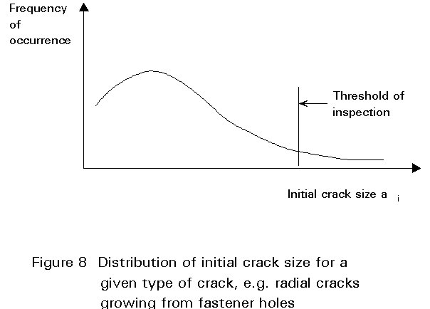
Presently, many specifications, in particular in the aeronautics field [4,7], detail NDI limits and require verification and certification of the capability of the contractor to detect cracks smaller than the specified NDI limits.
The sum of the load levels that a structure is expected to experience is determined by a projection of the amount of usage expected over its service life, in the various possible service conditions. The specific sequence of loads that is applied to the structure must be known for a precise crack growth damage analysis. Each loading event in the design, analyses or test load spectrum consists of a series of cycles that combine the deterministic and the probabilistic events describing the type of loading. The deterministic events include usual loading conditions (e.g. for a bridge structure, usual traffic loads, or for an aircraft takeoff, landing and some basic manoeuvre loads during each flight). Probabilistic events such as oversized loads (legal or illegal) for bridges, or rough field taxiing for aircraft, may occur periodically. Although it is possible to estimate, at least roughly, the number of times these events occur, their position in the load sequences may be determined only by means of probabilistic considerations.
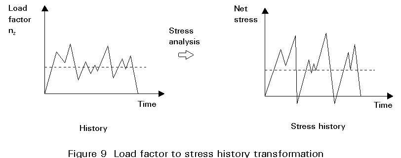
In developing the load spectrum for crack growth damage analysis, it is necessary to determine the stress history for each critical area in the structure. This is accomplished by determining, by means of stress analysis, the relationship between the load history and the local stress response, as illustrated in Figure 9 (from [4]).
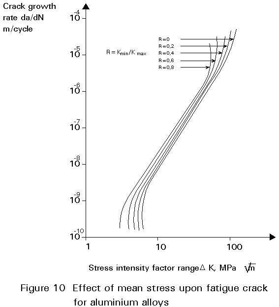
The material properties enter the damage integration procedure in the form of constant amplitude crack growth rate data. Crack growth data are generated in tests in the laboratory under constant amplitude loading cycles, on simple specimens with accepted characterizing stress intensity factors. Crack growth rate data are developed and correlated on the basis of growth rate (da/dN) as a function of the stress intensity factor range DK, (DK = Kmax - Kmin).
For a given DK, the crack growth rate increases with increasing stress ratio (R=smin/smax). Hence, the constant amplitude crack growth rate properties for a given material or alloy consist of a set of curves, as shown in Figure 10 (from [4]). It is important to notice that, for the fracture mechanics approach, given a DK:R combination, there is a unique value of the crack growth rate (da/dN), which is independent of geometry. When necessary, thermal or environmental effects can also be included in the crack growth rate data generated by laboratory testing.
The crack tip stress intensity factor (K) interrelates the crack geometry, the structural geometry and the load on the structure with the local stresses in the region of the crack tip. The stress intensity factor takes the form:
![]() (4)
(4)
where:
It can be seen that any number of combinations of the parameters Y(a), s and a can give rise to the same K. The crack growth analysis rests on the experimentally verified proposition that a given K gives rise to a certain crack growth rate, regardless of the way in which the parameters were combined to generate that K.
Considerable references are available which define experimental and mathematical solutions for stress intensity factors, for various structural configurations, both in closed or approximate form, e.g. [8].
Rewriting Equation (3) such that the integration is conducted between the initial crack length (ai) and any intermediate crack length (an) between ai and acr, the following expression is obtained:
an = ai + Sj = 1,N Daj (5)
where N is the number of cycles corresponding to the intermediate crack length an. The next cycle of the spectrum stress induces a crack length increment DaN+1. The damage integration model provides the analysis capability to determine this crack length increment. The growth increment DaN+1 is set equal to the constant amplitude crack growth rate, which in turn is expressed as a function of stress intensity factor range (DK) and stress ratio (R). These functions are determined by using the maximum and minimum stresses in the N+1 cycle of the given spectrum, and evaluating the correction factor Y(a), in Equation (4), associated with the given structural geometry at crack length an. After calculating the two crack tip parameters DK and R, they can be modified to account for the effect of prior loading history, using retardation models (e.g. [9]). Retardation models account for high-to-low load interaction effects, i.e. the phenomena whereby the growth of a crack is slowed by application of a high load in the spectrum. Failure to account for high-to-low load interaction via retardation models leads to conservative crack life predictions.
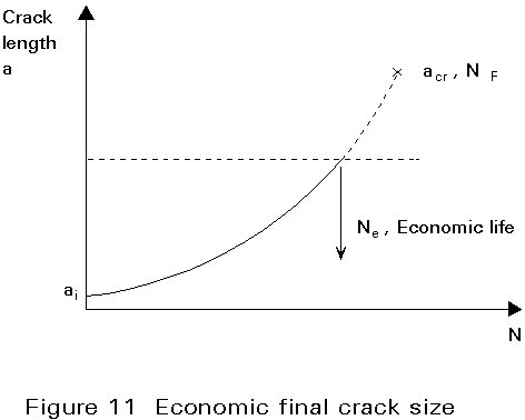
The final crack length, while estimating safety limits, may ordinarily be chosen as acr. However, durability considerations often dictate that the final crack size, aF, be chosen smaller than acr to represent re-work or repair limits. A choice of aF along these lines is shown in Figure 11 (from [4]).
[1] Guidance on Some Methods for the Derivation of Acceptance Levels for Defects in Fusion Welded Joints, British Standards Institution PD 6493, 1980.
[2] Rolfe and Barsom "Fatigue and Fracture Control in Structures", Prentice Hall Inc., Englewood Cliffs, N.J., 1977.
[3] Fisher J.W. "Fatigue and Fracture in Steel Bridges: Case Studies", J Wiley & Sons, New York 1984.
[4] Wood H.A., Engle R.M., Gallagher J. and Potter J.M. "Current Practice on Estimating Crack Growth Damage Accumulation with Specific Application to Structural Safety, Durability and Reliability", AFFDL-TR-75-32, March 1975.
[5] Gurney T.R., "Fatigue of Welded Structures", Cambridge University Press, Cambridge, UK, 1979.
[6] Madsen H.O., Tallin A.G., "Fatigue Reliability Updating Based on Inspection and Monitoring Results", Proceedings, IABSE Workshop on "Remaining Fatigue Life", Lausanne, 1990.
[7] ESACRACK User's Manual, ESA PSS-03-209, European Space Agency, Mechanical Systems Department, Structures and Mechanisms Division, Structural Design Section, Noordwijk, The Netherlands, 1989.
[8] Tada H., Irwin G.R., Paris P.C., "The Stress Analysis of Crack Handbook", Del. Research Corp., Hellertown, PA, 1973.
[9] Willemborg J., Engle R.M., and Wood H.A., "A Crack Growth Retardation Model using an Effective Stress Concept", AFFDL-TM-71-1-FBR, 1971.