ESDEP WG 8
PLATES AND SHELLS
To describe the buckling behaviour of stiffened shells and to analyse the different types of failure. A practical design procedure, based on the European recommendations, for stringer stiffened cylinders subject to axial load is presented.
Lecture 8.1: Introduction to Plate Behaviour and Design
Lecture 8.6: Introduction to Shell Structures
Lecture 8.7: Basic Analysis of Shell Structures
Lecture 8.8: Design of Unstiffened Cylinders
The buckling behaviour of stiffened shell structures is presented and the different types of failure are discussed. The shell has to be designed with respect to local shell buckling (limited to the shell panel between the stiffeners) and the stiffened panel buckling (or bay instability) in which both the shell panel and the stringers participate. Buckling of the stringers themselves must also be prevented. The design procedure relevant to this problem, as proposed by ECCS recommendations [1], is presented.
In Lectures 8.6 and Lecture 8.7 several aspects that influence the structural behaviour of shells have been introduced and the main principles of the shell theory have been presented. In particular it has been shown how the buckling strength of shell structures is influenced by residual stresses, geometric imperfections, and in some cases by the eccentricity of the load and by the boundary conditions. For these reasons axially compressed cylindrical shells often fail at a buckling strength considerably lower than the theoretical elastic value.
The buckling strength of cylindrical shells is often improved by the use of circumferential and/or longitudinal stiffeners. Their size, spacing and position on the outside or inside of the cylinder surface are factors that complicate the buckling behaviour of the shell.
In this lecture the general aspects of the buckling behaviour of stiffened shells are presented and, as an example of the application of practical design procedures, the buckling behaviour of stringer stiffened axially compressed cylinders is treated.
The shell may fail by overall buckling, by local buckling, or by a combination of the two. If the critical loads relevant to the first two kinds of buckling differ from each other, there is no interaction and, of course, the dominant mode of failure is the one relevant to the lowest buckling load. If the two phenomena occur at about the same load the interaction of the two types of buckling can theoretically cause a considerable reduction of the critical load. The buckling modes interact because of the non-linear relations governing post-buckling and cause a sharp drop in the post-buckling load bearing resistance [2,3].
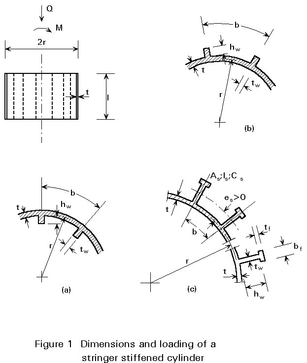
In general, the design procedure of a stiffened shell (Figure 1) subjected to axial compression and bending must consider the following types of failure:
The longitudinal stiffeners (stringers), which may be placed on the outside of the shell wall or on the inside, are frequently used to increase the axial or bending resistance of cylinders. In what follows the procedure proposed in the ECCS Recommendations [1] for the case of a cylindrical shell with longitudinal stiffeners and subject to meridional compression is examined. Ring stiffened or orthogonally stiffened shells are not treated here but the relevant design recommendations are similar to those presented here for stringer stiffened shells and may be found in [1].
In the ECCS design rules for a circular cylindrical shell with longitudinal stiffeners and subjected to axial compression and/or bending, it is assumed that the stringers are distributed uniformly along the circumference of the cylinder (Figure 1). The properties of the stiffeners are:
As is the cross-section area of the stiffener only
EIs is the bending stiffness of the stiffener only about the centroidal axis parallel to the cylinder wall
GCs is the torsional stiffness of the stiffener only
es is the distance between the shell midsurface and the stiffener centroid, (positive for an outside stiffener).
Cs may be evaluated by the formula for open sections consisting of flat strips
![]() (1)
(1)
The following recommendations apply when
As < 2bt, Is < 15 bt3, GCs < 10bt3E/[12(1-n2)] (2)
The initial imperfections of the shell panel between the stiffeners must be limited. The limitations are similar to those stated in Lecture 8.8 for unstiffened cylinders.
The inward and outward lack of straightness of the stiffener in the radial direction shall not exceed the following values:
![]() £ 0,0015 lg
when
£ 0,0015 lg
when ![]() ³ 0,06
(3)
³ 0,06
(3)
![]() £ 0,0015 lg and
£ 0,0015 lg and
![]() £ 0,01 lr
when 0 £
£ 0,01 lr
when 0 £ ![]() £ 0,06
(4)
£ 0,06
(4)
See (3) for details.
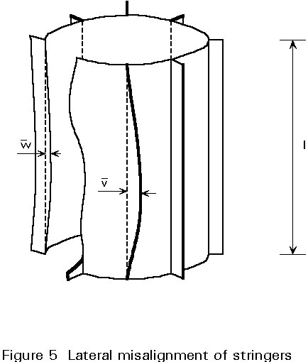
The limits given for ![]() also apply to the initial circumferential out-of-straightness
also apply to the initial circumferential out-of-straightness
![]() which is the lateral misalignment of the stiffeners attachment to the shell
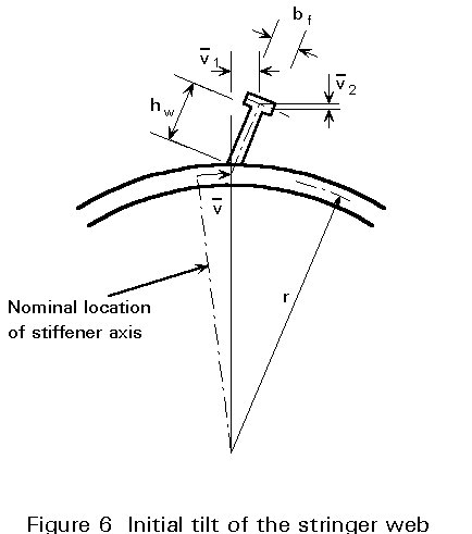
(Figure 5). Also the initial tilt of the stringer web and of the stringer flange
(Figure 6) shall be limited by:
which is the lateral misalignment of the stiffeners attachment to the shell
(Figure 5). Also the initial tilt of the stringer web and of the stringer flange
(Figure 6) shall be limited by:
![]() (5)
(5)
The design value of the extreme meridional acting stress is obtained from:
![]() (6)
(6)
where:
ts = t + ![]()
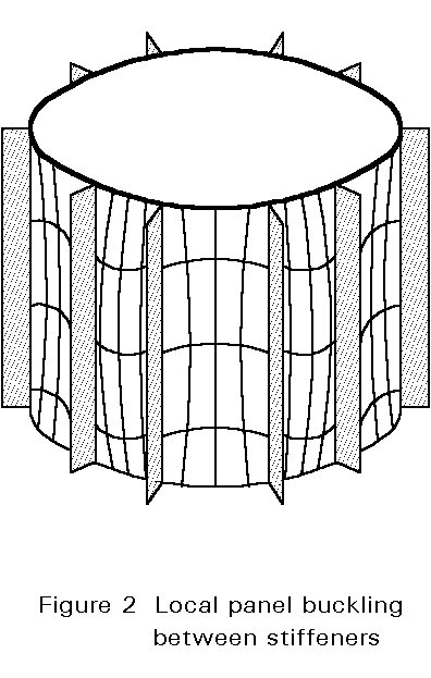
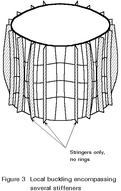
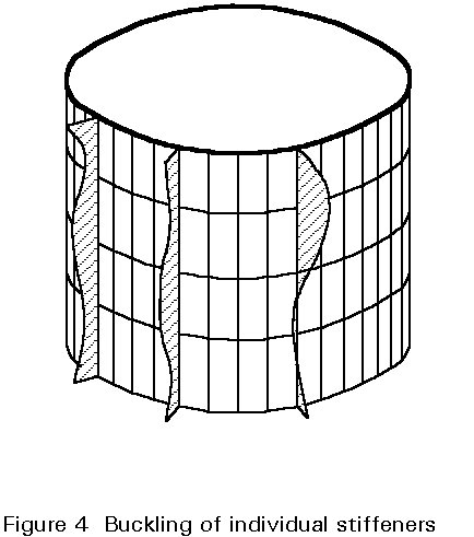
The shell must be designed with respect to local shell bucking (subscript l) which is limited to the shell panels between the stringer (Figure 2), and stiffened panel buckling (Figure 3) or bay instability (subscript p) in which both the shell panel and the stringers participate. Buckling of webs or flanges of the stiffeners themselves should be prevented by limiting the ratio of certain stringer cross-section dimensions (Figure 4).
The value of the compressive stress causing local shell buckling is denoted by sul while the value of the stress relevant to the stiffened panel buckling is denoted by sup. The design value sd of the highest meridional acting stress shall not exceed any of the two buckling stresses
s
d £ sul and sd £ sup (7)The elastic critical stress, scr, l, for a perfect shell panel between stringers may be taken equal to the higher of the two critical stresses for
a perfect complete cylinder |
scr, l, = 0,605E(t/r) |
[b/Ö(rt) > 2,44] |
(8) |
|
a perfectly flat plate |
scr, l = 3,6 E(t/b)2 |
[b/Ö(rt) £ 2,44] |
(9) |
The use of Equation (9) implies the neglect of the torsional rigidity of the stringers and of the post-buckling reserve of resistance of the supposedly flat panel.
The elastic local shell buckling stress, sul, for an imperfect panel is the higher of the stresses sul1 and sul2, provided that neither 4sul1 /3 nor sul2 exceeds 0,5fy; sul1 and sul2 are the stresses scr, l reduced to account for imperfections and, in the case of cylindrical panel buckling, also for imperfection sensitivity. They are in fact the values determined from Equations (8) and (9) reduced to (al scr, l / g) by a factor al and a partial safety factor g, where al accounts for the imperfections and g accounts for the imperfection sensitivity.
For a cylindrical panel, al is given by Equation (13) of [1], halved if the imperfection is equal to 0,02 lr and obtained by linear interpolation if is in the range between 0,01 lr and 0,02 lr, while g is taken equal to 4/3.
For plane panels the following factors are assumed:
a
l = 0,83 and g = 1,0Thus the following design values of the elastic shell buckling stress are obtained for an imperfect panel:
s
ul1 = ¾ao × 0,605E(t/r) (10)s
ul2 = 0,83 x 3,6 E (t/b)2 (11)When either 4sul1 /3 or sul2 exceeds 0,5 fy, plastic deformation comes into play and sul is the higher of the stresses sul1 and sul2 obtained from:
 if 0,605 ao E
 ![]() > 0,5 fy
(12)
> 0,5 fy
(12)
 if 0,83 x 3,6 E
 ![]() > 0,5 fy (13)
> 0,5 fy (13)
The elastic critical stress for a perfect stiffened cylindrical shell is given by:
 (14)
(14)
for n = 0 or n ³ 4 and m ³ 1
where ts is defined in Equation (6) and the quantities A11 to A33 are defined in the following way:
![]() (15)
(15)
![]()
![]()
![]()
![]()
![]()
![]() ;
; ![]()
![]() ;
; ![]()
The half wave number in the longitudinal direction, m, and the full wave number in the circumferential direction, n, must be chosen so that expression (14) is minimised. m and n are integers, but decimal values for m and n may be allowed in the minimizing processes. n = 0 represents axisymmetric buckling. n = 1 represents column buckling. When n = 2 or 3 the results of the minimization process may contain an error of the order of 20 to 25% on the unsafe side.
The critical stress resulting from Equation (14) is valid only if the stringers are spaced so closely that their number, ns, fulfils the condition
ns ³ 3,5 n (16)
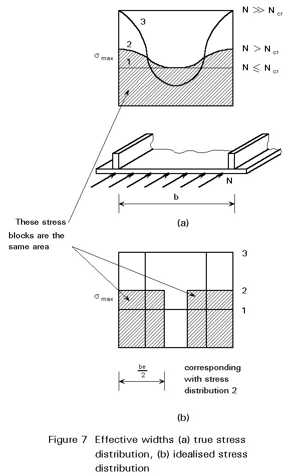
Although comparisons with experiments have shown that Equation (14) yields safe results even for numbers ns well below the limit of Equation (16), Equation (14) should be used with circumspection. Evaluation of the torsional stiffness, GCs, of the stringers, which has a marked influence on scr, p, is not always straightforward. Setting Cs = 0 in Equation (15), indicates the effective width of the panel (Figure 7). This concept was introduced first within the theory of buckling of plane panels (Lecture 8.1). The stress distribution in plan or curved panels becomes non-linear when the load exceeds the buckling limit (Figure 7a). The most common way of considering the post-buckling strength is to substitute an idealised stress distribution for the actual one such that the maximum stress and the average stress are conserved. See for example Figure 7b where the maximum stress smax is the same as in Figure 7a and the dashed areas have the same resultant. In practice, the effective panel width, be, may be obtained, but not explicitly, from
1,9tÖ(E/fy) £ be = bÖ(al scr,l/scr,p) £ b (17)
where al scr, l is the higher of the values 0,605 ao E(t/r) and 0,83x3,6E(t/b)2. Because in practical applications the stringers are spaced rather closely, only the influence of local shell buckling and of yielding on the effective width is considered in Equation (17).
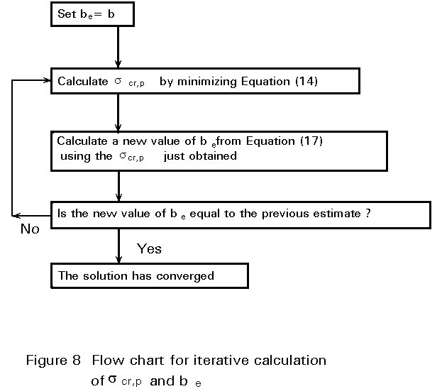
The lower limit of the effective width (Equation 17) was originally proposed by von Karman. If b £ 1,9 t ![]() , be should be set equal to b. When b>1,9t
, be should be set equal to b. When b>1,9t![]() , scr, p and be must be determined through the iterative procedure depicted in Figure 8 which can easily be implemented into a computer program. As a starting trial value of be take b, then the quantities A11 to A33 may be calculated, expression (14) minimized and, after the introduction of the tentative value scr, p into Equation (17), a new value of be may be obtained. The iteration process is stopped when successive values of be and scr,p are almost equal.
, scr, p and be must be determined through the iterative procedure depicted in Figure 8 which can easily be implemented into a computer program. As a starting trial value of be take b, then the quantities A11 to A33 may be calculated, expression (14) minimized and, after the introduction of the tentative value scr, p into Equation (17), a new value of be may be obtained. The iteration process is stopped when successive values of be and scr,p are almost equal.
Example
Evaluate scr, p for a mild steel cylinder having the following characteristics:
r/t = 1000
l/r = 1,6
ns = ns(min) outside flat bar stringer
E = 205000 Nmm-2 fy = 240 Nmm-2
As /(bt) = 0,5 hw /tw = 10
Applying the iterative procedure of Figure 8, which includes the effective width be according to Equation (17), yields the minimum scr, p = 202 Nmm-2 for m=1, n=11. The final effective width gives be = 0,4 b which, in this case, is von Karman's lower bound of Equation (17).
An alternative procedure for determining scr,p, which may be used when the stringers are flat bars, may be found in [1]. It is based on charts and contains also a non-iterative method to evaluate scr, p.
The results obtained so far are referred to the perfect panel. They must be corrected to include the effect of imperfections. The stiffened panel buckling stress for an imperfect stiffened cylinder may be obtained from:
s
up =where:
a
sp = 0,65 whena
sp = ao whena
sp may be obtained by linear interpolation in the intermediate range ofAs the stringer stiffeners decrease the imperfection sensitivity of meridionally compressed cylinders, the value asp is higher than ao when the stiffening effect is fairly substantial.
It has been shown [4] that external stiffeners make the shell more sensitive to the imperfections.
In the case of elastic-plastic buckling Equation (18) must be replaced by:
s
up = fy {1 - 0,4123[fy /(asp scr, p)]0,6} if asp scr, p > 0,5 fy (19)To prevent the local buckling of stringers (Figure 4), the ratios of the stringers cross-section dimensions shall be limited as follows:
hw /tw £ 0,35 ![]() for flat bar stiffeners with tw @ t
for flat bar stiffeners with tw @ t
hw /tw £ 1,1 ![]() and bf /tf £ 0,7
and bf /tf £ 0,7 ![]() for flanged stiffeners.
for flanged stiffeners.
a. local shell buckling (limited to the shell panel between the stiffeners)
b. stiffened panel buckling (in which the stiffeners and the panel participate)
c. bucking of the stiffeners themselves.
The procedure proposed by the ECCS [1] has been discussed in detail for stringer stiffened cylinders.
[1] European Convention for Construction Steelwork: "Buckling of Steel Shells - European Recommendations", Fourth Edition, ECCS, 1988.
[2] Samuelson, L. A., Vandepitte, D. and Paridaens, R., "The background to the ECCS recommendations for buckling of stringer stiffened cylinders", Proc. of Int. Coll. on Buckling of Plate and Shell Structures, Ghent, pp 513-522, 1987.
[3] Ellinas, C. P. and Croll, J. G. A., "Experimental and theoretical correlations for elastic buckling of axially compressed stringer stiffened cylinders", J Strain An., Vol. 18, pp 41-67, 1983.
[4] Hutchinson, J. W. and Amazigo, J. C., "Imperfection Sensitivity of Eccentrically Stiffened Cylindrical Shells", AIAA J, Vol. 5, No. 3, pp. 392-401, 1967.