ESDEP WG 8
PLATES AND SHELLS
To describe the buckling behaviour of cylindrical shells subjected to two different types of external loading, axial compression and external pressure, acting independently or in combination. To identify the key parameters influencing behaviour and to present a design procedure, based on the European recommendations.
None.
Lecture 8.6: Introduction to Shell Structures
Lecture 8.7: Basic Analysis of Shell Structures
The buckling behaviour of a cylindrical shell depends on several key parameters, such as geometry, material characteristics, imperfections and residual stresses, boundary conditions and type of loading. A reliable and economic procedure for the design of cylindrical shells against buckling should take into account all the above parameters, clearly specifying the range over which the design predictions are valid. The lecture presents the relevant design procedure contained in the ECCS Shell Buckling Recommendations [1] and briefly discusses alternative methods and identifies the important differences.
In Lectures 8.6 and Lecture 8.7 several aspects that influence the structural behaviour of shells have been introduced and the main principles of shell theory have been presented. In particular, it is worth recalling the following points:
i. The critical (bifurcation) buckling load of a perfect thin elastic cylinder under idealised loading, such as uniform axial compression, may be calculated using classical methods.
ii. The boundary conditions affect the critical buckling load and, for the same shell and type of loading, certain sets of boundary conditions can result in significantly lower buckling loads compared to those corresponding to other sets.
iii. Geometric imperfections caused by manufacturing are the main cause of the significant differences between critical buckling loads calculated using classical methods and experimental buckling loads. Even very small imperfections can cause a substantial drop in the buckling load of the shell.
iv. The sensitivity to imperfection depends primarily on the type of shell and type of loading, and, to some extent, on the boundary conditions. It may vary from moderate to extreme, even for the same shell geometry under different loading or boundary conditions. For example, a cylinder under axial compression is extremely sensitive to imperfections whilst the same shell under external pressure exhibits much lower imperfection sensitivity.
This lecture deals with the design of unstiffened cylinders. The buckling behaviour under two different types of loading, axial compression and external pressure, is first described qualitatively. An appropriate design procedure based on the ECCS Shell Buckling Recommendations [1] is then presented. The interaction behaviour for the two types of loading is also discussed.
General Considerations
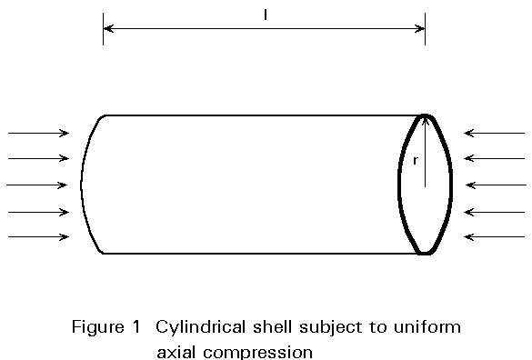
When a cylindrical shell is subjected to uniform axial compression (Figure 1) buckling can occur in two possible modes:
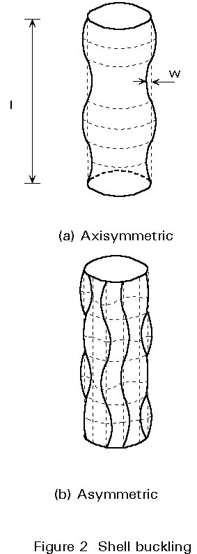
axisymmetric, where the displacements are constant around any circumferential section, Figure 2(a), or
asymmetric (also called chessboard), where waves are formed in both axial and circumferential directions, Figure 2(b).
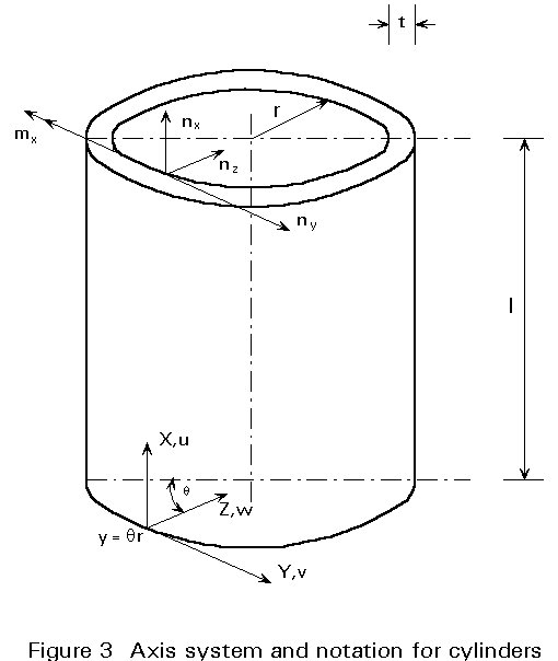
It can be shown theoretically that both modes of shell buckling correspond to the same critical buckling load. Assuming simply-supported boundary conditions (w = 0 and mx = 0, see Figure 3) that also preclude tangential displacements at both edges (v = 0) the critical elastic buckling stress, scr, is given by:
scr = ![]() (1)
(1)
where
E is the elastic modulus
t is the cylinder thickness
r is the cylinder radius
n
is Poisson's ratioIt is worth noting that the critical buckling stress is independent of the length of the cylinder.
Axisymmetric buckling is more often encountered in short and/or relatively thick cylinders. Asymmetric buckling is more common in thin and/or relatively long cylinders.
If one of the cylinder ends is free (w ¹ 0) the critical buckling stress drops to 38% of that given by Equation (1). If, however, the cylinder is clamped at both ends, rather than being simply supported, the increase in the critical buckling stress is not that significant from a design point of view.
On the other hand, the cylinder is sensitive to the tangential displacement at the boundaries [2,3]. If it is not prevented (v ¹ 0), the critical stress drops to about 50% of the value given by Equation (1).
Equation (1) cannot be used directly for design because cylindrical shells are extremely sensitive to imperfections under axial compression. Imperfection sensitivity is taken into account in design codes by introducing a "knock-down" factor, a, so that the product ascr represents the buckling load of the imperfect shell. In addition plasticity effects, which are important for a certain range of cylinder geometries, must be taken into account.
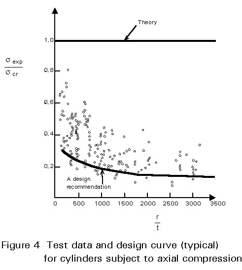
The "knock-down" factor is in general a function of shell geometry, loading conditions, initial imperfection amplitude and other factors and is normally evaluated from comparison with experimental results. The "knock-down" factor is selected so that a high percentage of experimental results (for example, 95%) should have buckling loads higher than the corresponding loads predicted by the design method. Figure 4 shows a typical distribution of test data for cylinders subjected to axial compression together with a typical design curve.
Due to the high sensitivity to imperfections, the design method should specify the maximum allowable level of imperfections. These tolerances are related to the imperfection amplitudes measured in the tests used in determining the appropriate "knock-down" factors. Clearly, the tolerances should not be so strict that they cannot be achieved using normal manufacturing processes. It should be noted that the use of experimental databases containing a large number of test specimens which are not representative of full-scale manufacturing, may lead to erroneous "knock-down" factors.
Ideally, the design method should also enable a designer to evaluate the buckling load of a cylinder with imperfections which exceed the allowable limits. Currently, very few design methods are valid for larger imperfections and the importance of adhering to the stated tolerances cannot be over-emphasised.
The experimental databases used by various codes in estimating "knock-down" factors can vary substantially. It is true to say that some design proposals are based on old, limited or inappropriate data. For this reason, design predictions for the buckling load of nominally identical cylinder geometries can vary substantially. References [4,5] present comparisons between various codes and attempt to explain the reasons for the observed differences.
The ECCS Design Procedure
The general philosophy adopted in the ECCS recommendations [1] is given in [6]. The design method for axially compressed cylinders is presented below, together with some clarifying comments.
The proposed method is valid for cylinders that satisfy w = v = 0 at the supports, i.e. radial and tangential displacements prevented, see Figure 3, and also for geometries that do not exceed the following geometric limit:
![]() (2)
(2)
This limit is imposed to preclude the possibility of overall column buckling interacting with shell buckling.
The cylinder should also satisfy the imperfection tolerances. They should be checked anywhere on the surface of the shell, using either a straight rod or a circular template, as shown schematically in Figure 5.
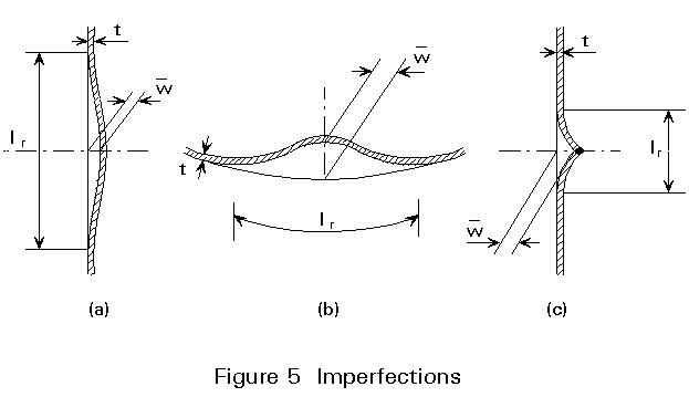
The length of the rod or template, lr, is related to the size of the potential
buckles [1]. The allowable imperfection, ![]() , is given by:
, is given by:
![]() = 0,01 lr (3)
= 0,01 lr (3)
The strength requirement for cylinders under uniform axial compression is given by:
sd £ su (4)
where sd is the applied axial compressive stress (characteristic load effect).
su is the design value of the buckling stress (characteristic resistance).
Thus, the objective is to determine the value of su, or, equivalently, the value of the ratio su/fy, where fy is the specified characteristic yield stress.
The proposed method is schematically shown in Figure 6, where su/fy is plotted against a slenderness parameter, l. This parameter is defined as:
l = ![]() (5)
(5)
where scr is the elastic critical buckling stress of a perfect cylinder given by Equation (1)
a is the "knock-down" factor, which accounts for the detrimental effect of imperfections, residual stresses and edge disturbances.
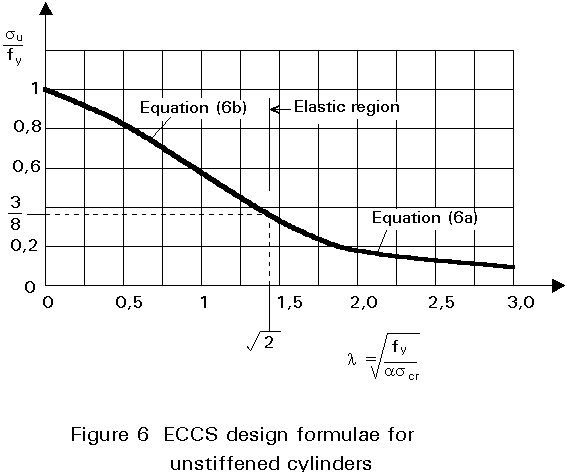
As can be seen from Figure 6, two regions are defined; the first, for which l ³
![]() , defines the region of elastic buckling, whereas l £
, defines the region of elastic buckling, whereas l £
![]() defines the region of plastic buckling.
defines the region of plastic buckling.
For l ³ ![]() or, equivalently, for ascr £ 0,5fy (i.e. when the buckling stress of the imperfect shell is less than half of the characteristic value of the yield stress), it is deemed that elastic buckling governs and the design curve is given by
or, equivalently, for ascr £ 0,5fy (i.e. when the buckling stress of the imperfect shell is less than half of the characteristic value of the yield stress), it is deemed that elastic buckling governs and the design curve is given by
su/fy = (1/g) (1/l2) (6a)
where 1/g is an additional safety factor introduced for this type of geometry and loading to account for the extreme sensitivity to imperfections and the unfavourable post-buckling behaviour; a value of 3/4 is recommended for l/g .
For l £ ![]() (ascr ³ 0,5fy), material non-linearities also play a role (plastic buckling) and the design curve is given by:
(ascr ³ 0,5fy), material non-linearities also play a role (plastic buckling) and the design curve is given by:
su/fy = 1 - 0,4123 l1,2 (6b)
The "knock-down" factor a, which appears in Equation (5), has been derived from comparisons with experimental results and is determined from the following equations, which are plotted in Figure 7. These equations are applicable if the amplitude of the imperfections anywhere on the shell is less than or equal to the value given by Equation (3). It is worth pointing out the dependence of a on cylinder slenderness, r/t.
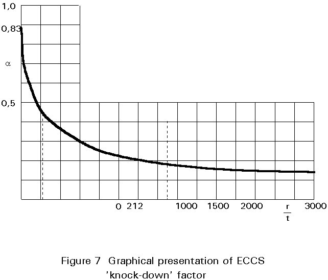
a =  for r/t < 212 (7a)
a =  for r/t > 212 (7b)
Details of the experimental database used in deriving these equations are presented in [7].
It is also worth noting in Figure 6 that su/fy approaches unity for very stocky cylinders (l close to 0) and, furthermore, that there is a smooth transition from elastic to plastic buckling at the change-over of formulae, as would be expected from a physical point of view.
If the maximum amplitude of the actual cylinder imperfections is twice the value given by Equation (3) then the value of the "knock-down" factor given by Equations (7a) and (7b) is halved. When 0,01 lr £
![]() £ 0,02 lr linear interpolation between a and a/2 gives the required "knock-down" factor.
£ 0,02 lr linear interpolation between a and a/2 gives the required "knock-down" factor.
Although a slight, practically unavoidable unevenness of the supports of the cylinder is covered by the "knock-down" factor a, care must be exercised to introduce the compressive forces uniformly into the cylinder and to avoid edge disturbances. The design method does not cover cylinders loaded over part of their circumference, e.g. a cylinder resting on a number of point supports.
Finally, the above procedure covers shell buckling design of cylinders satisfying the limit imposed by Equation (2). However, very short cylinders fail by plate-type buckling which depends on the length of the cylinder, rather than by shell buckling. In this case, meridional strips of the cylinder wall buckle like strips of a "wide" plate under compression and do not exhibit the sensitivity to imperfections associated with shell-type behaviour.
In this case su is given by:
For sE £ 0,5 fy (elastic buckling)
su = sE (8a)
For sE ³ 0,5 fy (plastic buckling)
su = fy  (8b)
(8b)
where sE is the elastic critical buckling stress of a "wide" plate of length l and thickness t, given by
sE = ![]() (9)
(9)
In general, for any particular geometry, both Equations (6) and (8) should be evaluated and the higher value taken for su. However, Equation (8) gives a value higher than Equation (6) only for very short cylinders. It is quite easy to work out that for elastic buckling, i.e. comparing Equation (6a) and Equation (8a), this is true when
![]() <
< ![]() (10)
(10)
General Considerations
External pressure may be applied either purely radially, as "external pressure loading" (Figure 8(a)), or it may be applied all round the cylindrical shell, that is both radially and axially (Figure 8(b)) as "external hydrostatic pressure loading".
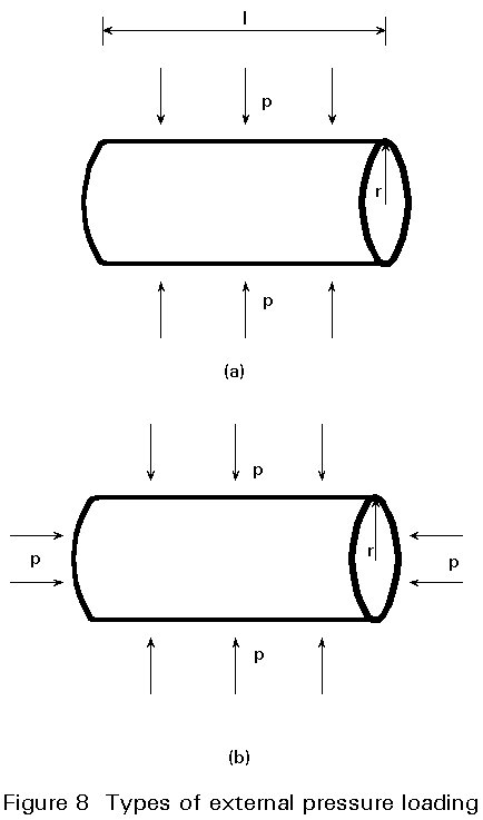
For external lateral pressure, the hoop stress sq , in the pre-buckling state away from the supports is related to the applied pressure, p, by a simple expression:
sq = (r/t) p (11)
In this case, the axial stress sx = 0.
For external hydrostatic pressure, the hoop stress is again given by Equation (11) but the axial stress sx = 0,5sq .
In the latter case, the cylinder is, in fact, subjected to combined axial and pressure loading. This case will be examined in Section 4, where the complete interaction behaviour is described.
Assuming classical simply supported conditions (v = w = 0 and nx = mx = 0, at the supports) and neglecting the effect of boundary conditions on the pre-buckling state, it is possible to derive the elastic critical buckling pressure of the cylinder. This is known as the von Mises critical pressure, pcr
pcr = 
 (12)
(12)
As can be seen, pcr depends on shell geometry, and in particular the ratios l/r and t/r, the material characteristics, E and n, and the number of complete circumferential waves, n, forming at buckling. Thus, for a given geometry and material, Equation (12) must be minimised with respect to n in order to obtain the lowest pcr.
Simpler expressions for pcr have also been developed, for example using the so-called Donnell equations for "shallow" shells giving good results provided that the value of n minimising pcr is greater than two [3].
For reasons similar to those mentioned in Section 2, namely sensitivity to imperfections and plasticity effects, the value obtained from Equation (12) is not directly suitable for design.
The sensitivity to imperfections of cylindrical shells under external pressure is not as severe as under axial compression. This difference has been demonstrated both theoretically and experimentally and is reflected in the "knock-down" factors used in design.
Despite the reduced imperfection sensitivity, considerable differences exist between various codes [5], possibly due to the different theoretical approaches adopted (see also [4]).
The ECCS Design Procedure
The procedure described below applies only to uniform external pressure. Pressure due to wind loading is not covered by this method. Furthermore, cylinders should be circular to within 0,5% of the radius measured from the true centre. At least 24 equally spaced points around the circumference should be chosen in order to establish whether the cylinder satisfies this out-of-roundness tolerance. Finally, the procedure is valid for cylinders having the "classical" simple supports during buckling (i.e. nx = v = w = mx = 0) and does not apply to cylinders which have one or two free edges.
The strength requirement is given by:
pd £ pu (13)
where pd is the applied uniform external pressure (characteristic load effect).
pu is the design pressure (characteristic resistance).
The first step consists of calculating the pressure py, at which the hoop stress at cylinder mid-length reaches the yield stress. From Equation (11), it follows that
py = (t/r)fy (14)
Clearly, when pu = py the cylinder is so stocky that buckling plays no part in determining the design pressure.
Then, pcr, the elastic critical buckling pressure is calculated using a formula, which is a slight modification of the von Mises equation (12), as discussed in [8]. The equation has the following form:
pcr = E (t/r) bmin (15)
where bmin is the minimum value of b with respect to n. The expression for b is given by
b = 
+
(16)
A chart is also given in [1] which can be used in the evaluation of bmin. Furthermore, bmin may be approximately estimated from
bmin =  (17)
(17)
for l/r ³ 0,5.
Having calculated py and pcr, an appropriate slenderness parameter is defined by
l = ![]() (18)
(18)
If l ³ 1, elastic buckling takes place and the design pressure is determined from
pu/py = a/l2 (19)
where a is the "knock-down" factor to account for the imperfection sensitivity.
From the results of about 700 tests, a = 0,5. Notice that, in contrast to the "knock-down" factor relevant to axial compression, in this case, a is independent of shell slenderness, r/t.
In the plastic region, 0 £ l £ 1, the value of pu/py is obtained from the curve shown in Figure 9.
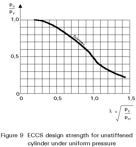
This curve is closely approximated by the following expression:
pu/ py = 1/(1+l2) (20)
Buckling of unstiffened cylinders under combined loading is of considerable interest to designers. For example, combined axial compression and lateral pressure is often encountered in offshore design practice.
The available design recommendations are mostly empirical. They are based on a much more limited number of experiments compared to the number used for the two basic cases reviewed in Sections 2 and 3.
Buckling under combined axial and pressure loading can be quite sensitive to imperfections, especially in cases where the loading is dominated by axial compression.
The ECCS recommendations [1], in common with some other codes, adopt a simple piece-wise linear interaction based on the buckling strength under axial compression or external pressure acting alone. The cylinder must be constrained so that v = w = 0 at both ends. Furthermore, the cylinder must comply with the imperfection tolerances outlined in Sections 2 and 3.
The interaction curve is shown in Figure 10.
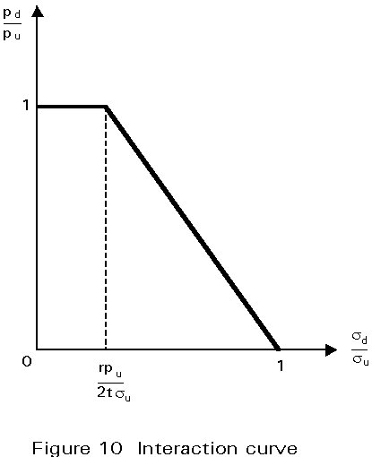
Any combination of sd/su and pd/pu falling within the region defined by the two straight lines is safe. Thus, the applied loads (sd, pd) should satisfy the following two conditions:
I: sd £ su (21a)
II: ![]() £
1 if sd £
£
1 if sd £ ![]() (21b)
(21b)
or
 £
1 if sd >
£
1 if sd > ![]() (21c)
(21c)
Equation (21b) states that if the applied axial compression is less than or equal to that produced by applying uniform hydrostatic pressure, then the design pressure corresponding to uniform external pressure may be achieved. A reduction due to the simultaneous presence of axial compression is not deemed necessary. If however, the axial compression is higher than this limiting value then the design strength is reduced linearly as expressed by Equation (21c).
Experimental evidence has shown that this interaction diagram is conservative.
× the imperfection sensitivity, appropriate to the geometry, loading and boundary conditions and hence, derive appropriate "knock-down" factors using reliable experimental data.
× the limitations that must be imposed on allowable imperfections due to available experimental data and the characteristics of the manufacturing processes.
× the interaction between elastic buckling and yielding.
× the effect of boundary conditions.
1. Determine the elastic critical buckling stress of the perfect shell.
2. Calculate the "knock-down" factor and, hence, the buckling stress of the imperfect shell.
3. Depending on shell slenderness, modify the value from step (2) to account for plastic buckling.
[1] ECCS - European Convention for Constructional Steelwork - Buckling of Steel Shells European Recommendations, Fourth Edition, 1988.
[2] Timoshenko S P and Gere J M, Theory of Elastic Stability, McGraw-Hill, 1982.
[3] Brush D O and Almroth B O, Buckling of Bars, Plates and Shells, McGraw-Hill, 1975.
[4] Beedle L S, Stability of Metal Structures: A World View, Structural Stability Research Council, 1991.
[5] Ellinas C P, Supple W J and Walker A C, Buckling of Offshore Structures, Granada, 1984.
[6] Samuelson L A, "The ECCS Recommendations on Shell Stability; Design Philosophy and Practical Applications", in "Buckling of Shell Structures, on Land, in the Sea and in the Air", J F Jullien (ed), Elsevier Applied Science, 1991, pp. 261-264.
[7] Vandepitte D and Rathe J, "Buckling of Circular Cylindrical Shells under Axial Load in the Elastic-Plastic Region", Der Stahlbau, Heft 12, 1980, S. 369-373.
[8] Kendrick, S B, "Collapse of stiffened cylinders under external pressure", Paper C190/72 in proc. Conf. on Vessels under Buckling Conditions, Instn of Mech. Engrs., London, 1972.