ESDEP WG 8
PLATES AND SHELLS
To discuss the load distribution, stability and ultimate resistance of unstiffened plates under in-plane and out-of-plane loading.
Lecture 8.1: Introduction to plate behaviour and design
Lecture 8.3: Stiffened Plates
Lectures 8.4: Plate Girder Behaviour and Design I and II
Lecture 8.6: Introduction to Shell Structures
The load distribution for unstiffened plate structures loaded in-plane is discussed. The critical buckling loads are derived using Linear Elastic Theory. The effective width method for determining the ultimate resistance of the plate is explained as are the requirements for adequate finite element modelling of a plate element. Out-of-plane loading is also considered and its influence on the plate stability discussed.
Thin-walled members, composed of thin plate panels welded together, are increasingly important in modern steel construction. In this way, by appropriate selection of steel quality, geometry, etc., cross-sections can be produced that best fit the requirements for strength and serviceability, thus saving steel.
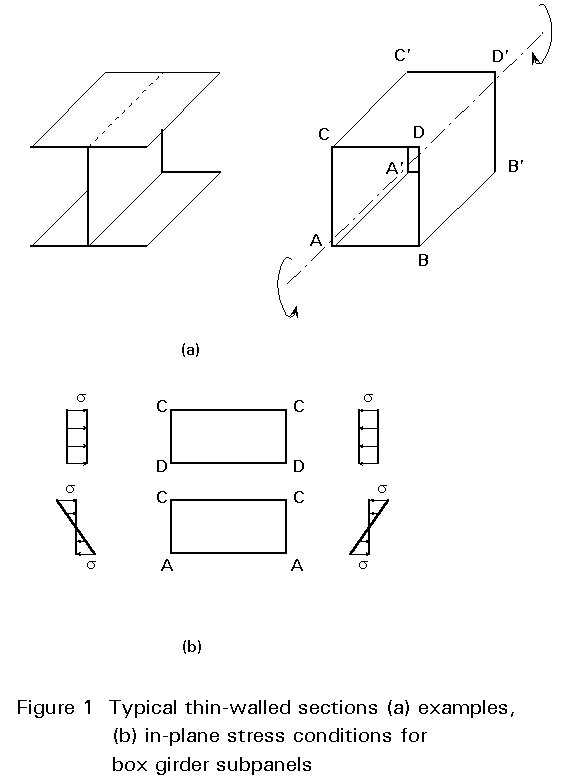
Recent developments in fabrication and welding procedures allow the automatic production of such elements as plate girders with thin-walled webs, box girders, thin-walled columns, etc. (Figure 1a); these can be subsequently transported to the construction site as prefabricated elements.
Due to their relatively small thickness, such plate panels are basically not intended to carry actions normal to their plane. However, their behaviour under in-plane actions is of specific interest (Figure 1b). Two kinds of in-plane actions are distinguished:
a) those transferred from adjacent panels, such as compression or shear.
b) those resulting from locally applied forces (patch loading) which generate zones of highly concentrated local stress in the plate.
The behaviour under patch action is a specific problem dealt with in the lectures on plate girders (Lectures 8.5.1 and 8.5.2). This lecture deals with the more general behaviour of unstiffened panels subjected to in-plane actions (compression or shear) which is governed by plate buckling. It also discusses the effects of out-of-plane actions on the stability of these panels.
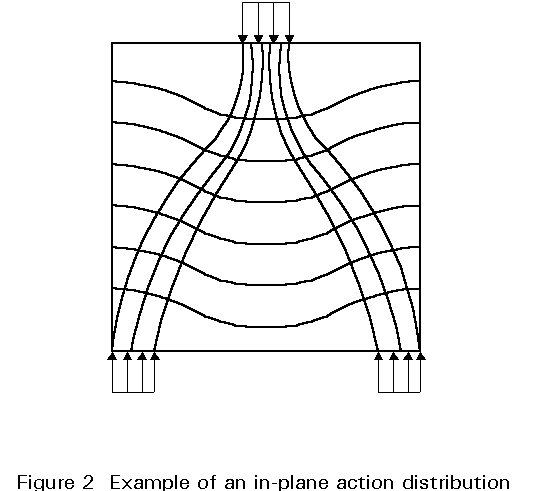
The stress distribution in plates that react to in-plane loading with membrane stresses may be determined, in the elastic field, by solving the plane stress elastostatic problem governed by Navier's equations, see Figure 2.
where:
u = u(x, y), v = v(x, y): are the displacement components in the x and y directions
neff = 1/(1 + n) is the effective Poisson's ratio
G: is the shear modulus
X = X(x, y), Y = Y(x, y): are the components of the mass forces.
The functions u and v must satisfy the prescribed boundary (support) conditions on the boundary of the plate. For example, for an edge parallel to the y axis, u= v = 0 if the edge is fixed, or sx = txy = 0 if the edge is free to move in the plane of the plate.
The problem can also be stated using the Airy stress function, F = F(x, y), by the following biharmonic equation:
Ñ
4F = 0This formulation is convenient if stress boundary conditions are prescribed. The stress components are related to the Airy stress function by:
![]() ;
; ![]() ;
;
![]()
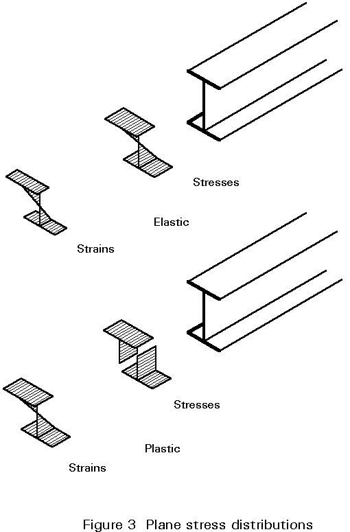
For slender plated structures, where the plates are stressed as membranes, the application of Airy's stress function is not necessary due to the hypothesis of plane strain distributions, which may be used in the elastic as well as in the plastic range, (Figure 3).
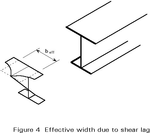
However, for wide flanges of plated structures, the application of Airy's stress function leads to significant deviations from the plane strain hypothesis, due to the shear lag effect, (Figure 4). Shear lag may be taken into account by taking a reduced flange width.
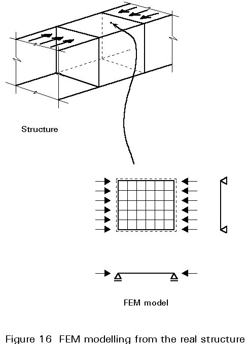
When using finite element methods for the determination of the stress distribution, the plate can be modelled as a perfectly flat arrangement of plate sub-elements. Attention must be given to the load introduction at the plate edges so that shear lag effects will be taken into account. The results of this analysis can be used for the buckling verification.
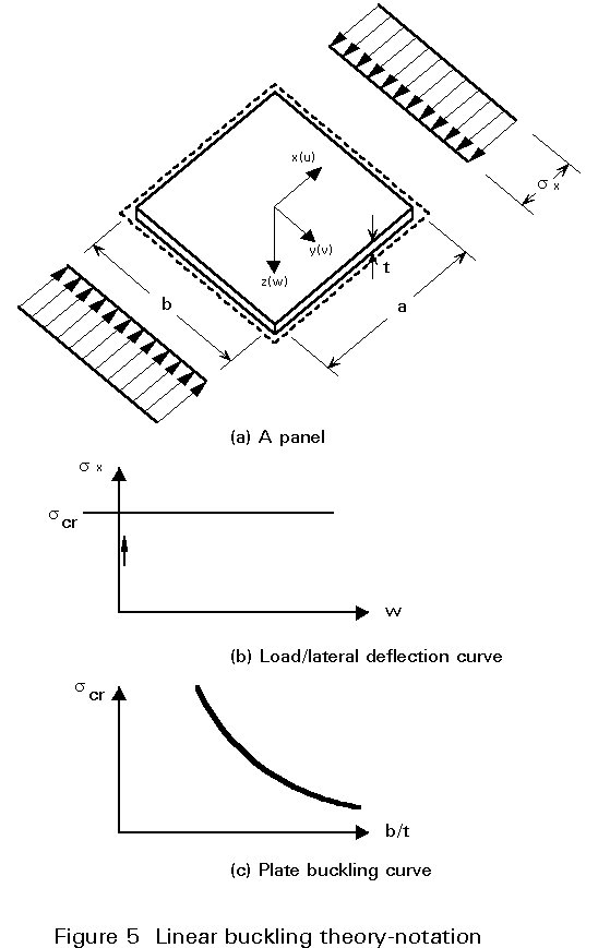
The buckling of plate panels was investigated for the first time by Bryan in 1891, in connection with the design of a ship hull [1]. The assumptions for the plate under consideration (Figure 5a), are those of thin plate theory (Kirchhoff's theory, see [2-5]):
a) the material is linear elastic, homogeneous and isotropic.
b) the plate is perfectly plane and stress free.
c) the thickness "t" of the plate is small compared to its other dimensions.
d) the in-plane actions pass through its middle plane.
e) the transverse displacements w are small compared to the thickness of the plate.
f) the slopes of the deflected middle surfaces are small compared to unity.
g) the deformations are such that straight lines, initially normal to the middle plane, remain straight lines and normal to the deflected middle surface.
h) the stresses normal to the thickness of the plate are of a negligible order of magnitude.
Due to assumption (e) the rotations of the middle surface are small and their squares can be neglected in the strain displacement relationships for the stretching of the middle surface, which are simplified as:
ex = ∂u/∂x , p2E/l2 gxy = ∂u/∂y + ∂v/∂x (1)
An important consequence of this assumption is that there is no stretching of the middle surface due to bending, and the differential equations governing the deformation of the plate are linear and uncoupled. Thus, the plate equation under simultaneous bending and stretching is:
DÑ4w = q-kt{sx ∂2w/∂x2 + 2txy ∂2w/∂x∂y + sy ∂2w/∂y2} (2)
where D = Et3/12(1 - n2) is the bending stiffness of the plate having thickness t, modulus of elasticity E, and Poisson's ratio n; q = q(x,y) is the transverse loading; and k is a parameter. The stress components, sx, sy, txy are in general functions of the point x, y of the middle plane and are determined by solving independently the plane stress elastoplastic problem which, in the absence of in-plane body forces, is governed by the equilibrium equations:
∂sx/∂x + ∂txy/∂y = 0, ∂txy/∂x + ∂sy/∂y = 0 (3)
supplemented by the compatibility equation:
Ñ
2 (sx + sy) = 0 (4)Equations (3) and (4) are reduced either to the biharmonic equation by employing the Airy stress function:
Ñ
4 F = 0 (5)defined as:
sx = ∂2F/∂y2 , sy = ∂2F/∂x2 , txy = -∂2F/∂x∂y
or to the Navier equations of equilibrium, if the stress displacement relationships are employed:
Ñ2 + [1/(1-![]() )]
∂/∂x {∂u/∂x + ∂v/∂y}
=
0
)]
∂/∂x {∂u/∂x + ∂v/∂y}
=
0
Ñ2 + [1/(1-![]() )]
∂/∂y {∂u/∂x + ∂v/∂y}
=
0
(6)
)]
∂/∂y {∂u/∂x + ∂v/∂y}
=
0
(6)
where ![]() = n/(1 +
n) is the effective Poisson's ratio.
= n/(1 +
n) is the effective Poisson's ratio.
Equation (5) is convenient if stress boundary conditions are prescribed. However, for displacement or mixed boundary conditions Equations (6) are more convenient. Analytical or approximate solutions of the plane elastostatic problem or the plate bending problem are possible only in the case of simple plate geometries and boundary conditions. For plates with complex shape and boundary conditions, a solution is only feasible by numerical methods such as the finite element or the boundary element methods.
Equation (2) was derived by Saint-Venant. In the absence of transverse loading (q = 0), Equation (2) together with the prescribed boundary (support) conditions of the plate, results in an eigenvalue problem from which the values of the parameter k, corresponding to the non-trivial solution (w ¹ 0), are established. These values of k determine the critical in-plane edge actions (scr, tcr) under which buckling of the plate occurs. For these values of k the equilibrium path has a bifurcation point (Figure 5b). The edge in-plane actions may depend on more than one parameter, say k1, k2,...,kN, (e.g. sx, sy and txy on the boundary may increase at different rates). In this case there are infinite combinations of values of ki for which buckling occurs. These parameters are constrained to lie on a plane curve (N = 2), on a surface (N = 3) or on a hypersurface (N > 3). This theory, in which the equations are linear, is referred to as linear buckling theory.
Of particular interest is the application of the linear buckling theory to rectangular plates, subjected to constant edge loading (Figure 5a). In this case the critical action, which corresponds to the Euler buckling load of a compressed strut, may be written as:
s
cr = ks sE or tcr = kt sE (7)where sE = ![]() (8)
(8)
and ks, kt are dimensionless buckling coefficients.
Only the form of the buckling surface may be determined by this theory but not the magnitude of the buckling amplitude. The relationship between the critical stress scr, and the slenderness of the panel l = b/t, is given by the buckling curve. This curve, shown in Figure 5c, has a hyperbolic shape and is analogous to the Euler hyperbola for struts.
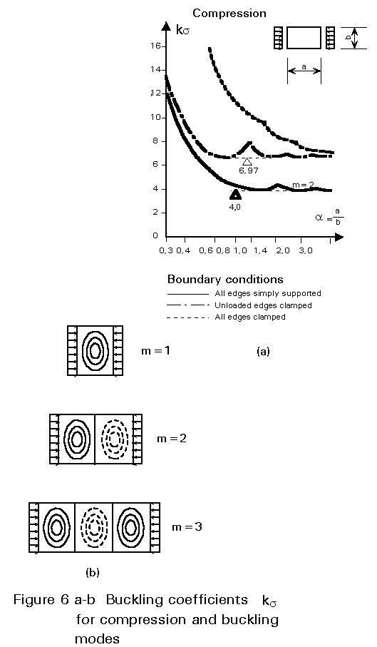
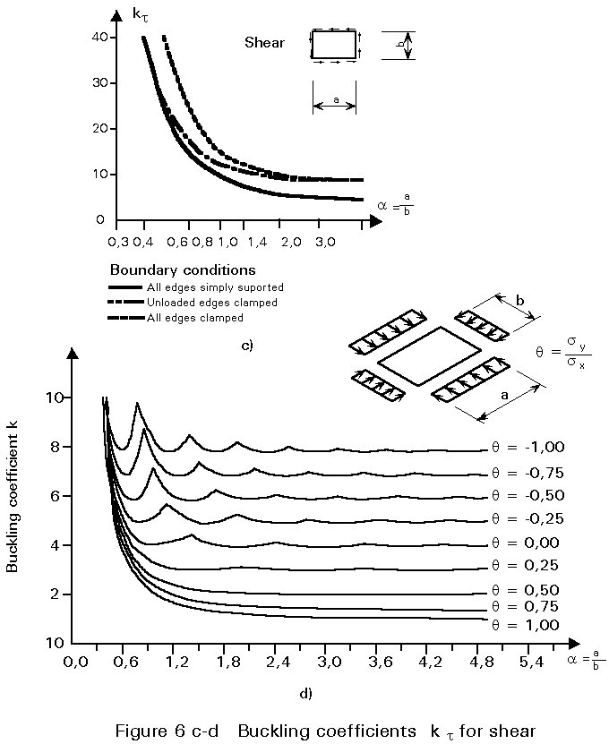
The buckling coefficients, "k", may be determined either analytically by direct integration of Equation (2) or numerically, using the energy method, the method of transfer matrices, etc. Values of ks and kt for various actions and support conditions are shown in Figure 6 as a function of the aspect ratio of the plate a =a/b. The curves for ks have a "garland" form. Each garland corresponds to a buckling mode with a certain number of waves. For a plate subjected to uniform compression, as shown in Figure 6a, the buckling mode for values of a < Ö2, has one half wave, for values Ö2 < a < Ö6, two half waves, etc. For a = Ö2 both buckling modes, with one and two half waves, result in the same value of ks . Obviously, the buckling mode that gives the smallest value of k is the decisive one. For practical reasons a single value of ks is chosen for plates subjected to normal stresses. This is the smallest value for the garland curves independent of the value of the aspect ratio. In the example given in Figure 6a, ks is equal to 4 for a plate which is simply supported on all four sides and subjected to uniform compression.
Combination of stresses sx, sy and t
For practical design situations some further approximations are necessary. They are illustrated by the example of a plate girder, shown in Figure 7.
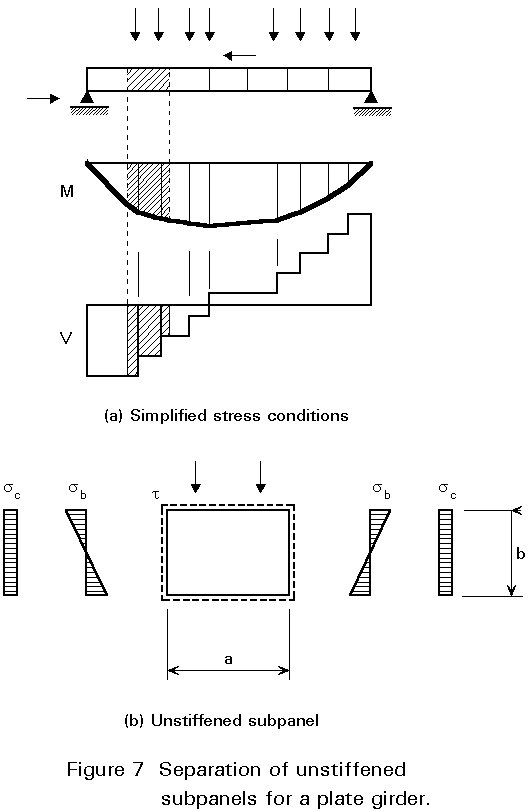
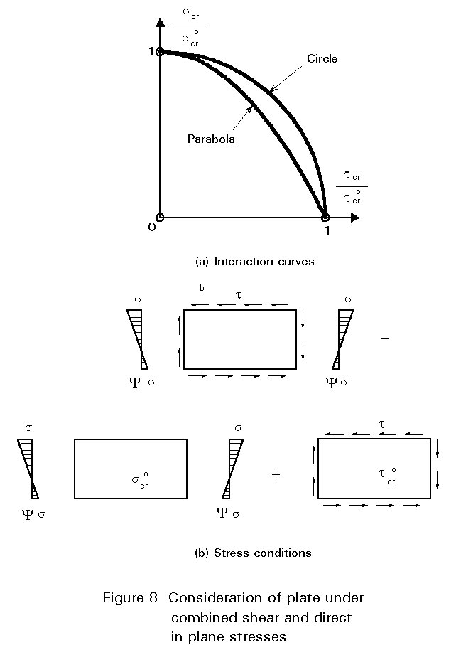
The normal and shear stresses, sx and t respectively, at the opposite edges of a subpanel are not equal, since the bending moments M and the shear forces V vary along the panel. However, M and V are considered as constants for each subpanel and equal to the largest value at an edge (or equal to the value at some distance from it). This conservative assumption leads to equal stresses at the opposite edges for which the charts of ks and kt apply. The verification is usually performed for two subpanels; one with the largest value of sx and one with the largest value of t. In most cases, as in Figure 7, each subpanel is subjected to a combination of normal and shear stresses. A direct determination of the buckling coefficient for a given combination of stresses is possible; but it requires considerable numerical effort. For practical situations an equivalent buckling stress screq is found by an interaction formula after the critical stresses screq and tcro , for independent action of s and t have been determined. The interaction curve for a plate subjected to normal and shear stresses, sx and t respectively, varies between a circle and a parabola [6], depending on the value of the ratio ψ of the normal stresses at the edges (Figure 8).
This relationship may be represented by the approximate equation:
 (9)
(9)
For a given pair of applied stresses (s, t) the factor of safety with respect to the above curve is given by:
![]() =
=  (10)
(10)
The equivalent buckling stress is then given by:
screq = gcreq Ö{s2 + 3t2} (11)
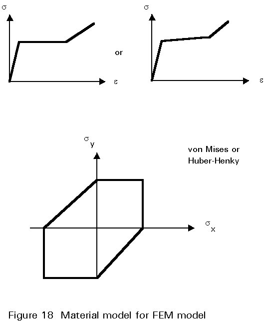
where the von Mises criterion has been applied.
For simultaneous action of sx, sy and t similar relationships apply.
General
The linear buckling theory described in the previous section is based on assumptions (a) to (h) that are never fulfilled in real structures. The consequences for the buckling behaviour when each of these assumptions is removed is now discussed.
The first assumption of unlimited linear elastic behaviour of the material is obviously not valid for steel. If the material is considered to behave as linear elastic-ideal plastic, the buckling curve must be cut off at the level of the yield stress sy (Figure 9b).
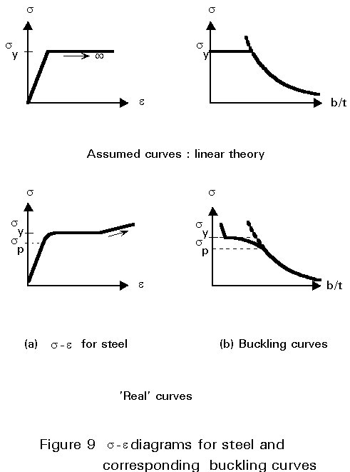
When the non-linear behaviour of steel between the proportionality limit sp and the yield stress sy is taken into account, the buckling curve will be further reduced (Figure 9b). When strain hardening is considered, values of scr larger than sy, as experimentally observed for very stocky panels, are possible. In conclusion, it may be stated that the removal of the assumption of linear elastic behaviour of steel results in a reduction of the ultimate stresses for stocky panels.
The second and fourth assumptions of a plate without geometrical imperfections and residual stresses, under symmetric actions in its middle plane, are also never fulfilled in real structures. If the assumption of small displacements is still retained, the analysis of a plate with imperfections requires a second order analysis. This analysis has no bifurcation point since for each level of stress the corresponding displacements w may be determined. The equilibrium path (Figure 10a) tends asymptotically to the value of scr for increasing displacements, as is found from the second order theory.
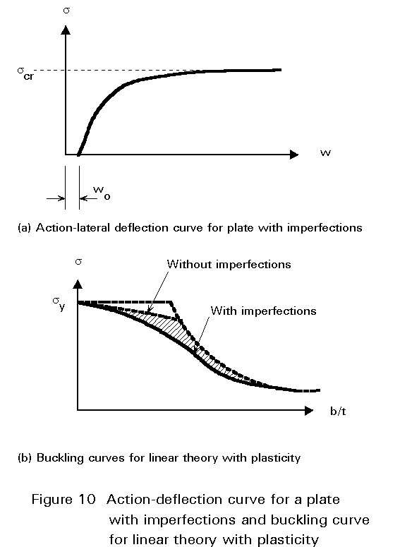
However the ultimate stress is generally lower than scr since the combined stress due to the buckling and the membrane stress is limited by the yield stress. This limitation becomes relevant for plates with geometrical imperfections, in the region of moderate slenderness, since the value of the buckling stress is not small (Figure 10b). For plates with residual stresses the reduction of the ultimate stress is primarily due to the small value of sp (Figure 9b) at which the material behaviour becomes non-linear. In conclusion it may be stated that imperfections due to geometry, residual stresses and eccentricities of loading lead to a reduction of the ultimate stress, especially in the range of moderate slenderness.
The assumption of small displacements (e) is not valid for stresses in the vicinity of scr as shown in Figure 10a. When large displacements are considered, Equation (1) must be extended to the quadratic terms of the displacements. The corresponding equations, written for reasons of simplicity for a plate without initial imperfections, are:
 (12)
(12)
This results in a coupling between the equations governing the stretching and the bending of the plate (Equations (1) and (2)).
 (13a)
(13a)
 (13b)
(13b)
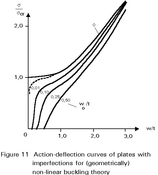
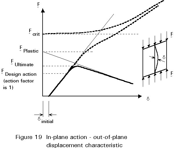
where F is an Airy type stress function. Equations (13) are known as the von Karman equations. They constitute the basis of the (geometrically) non-linear buckling theory. For a plate without imperfections the equilibrium path still has a bifurcation point at scr, but, unlike the linear buckling theory, the equilibrium for stresses s > scr is still stable (Figure 11). The equilibrium path for plates with imperfections tends asymptotically to the same curve. The ultimate stress may be determined by limiting the stresses to the yield stress. It may be observed that plates possess a considerable post-critical carrying resistance. This post-critical behaviour is more pronounced the more slender the plate, i.e. the smaller the value of scr.
Buckling curve
For the reasons outlined above, it is evident that the Euler buckling curve for linear buckling theory (Figure 6c) may not be used for design. A lot of experimental and theoretical investigations have been performed in order to define a buckling curve that best represents the true behaviour of plate panels. For relevant literature reference should be made to Dubas and Gehri [7]. For design purposes it is advantageous to express the buckling curve in a dimensionless form as described below.
The slenderness of a panel may be written according to (7) and (8) as:
lp = (b/t) Ö{12(1-n2)/ks} = pÖ(E/scr) (14)
If a reference slenderness given by:
ly = pÖ(E/fy) (15)
is introduced, the relative slenderness becomes:
![]() p
= lp/ly
= Ö(sy/scr)
(16)
p
= lp/ly
= Ö(sy/scr)
(16)
The ultimate stress is also expressed in a dimensionless form by introducing a reduction factor:
k = su /sy (17)
Dimensionless curves for normal and for shear stresses as proposed by Eurocode 3 [8] are illustrated in Figure 12.
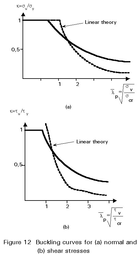
These buckling curves have higher values for large slendernesses than those of the Euler curve due to post critical behaviour and are limited to the yield stress. For intermediate slendernesses, however, they have smaller values than those of Euler due to the effects of geometrical imperfections and residual stresses.
Although the linear buckling theory is not able to describe accurately the behaviour of a plate panel, its importance should not be ignored. In fact this theory, as in the case of struts, yields the value of an important parameter, namely
![]() p, that is used for the determination of the ultimate stress.
p, that is used for the determination of the ultimate stress.
Effective width method
This method has been developed for the design of thin walled sections subjected to uniaxial normal stresses. It will be illustrated for a simply-supported plate subjected to uniform compression (Figure 13a).
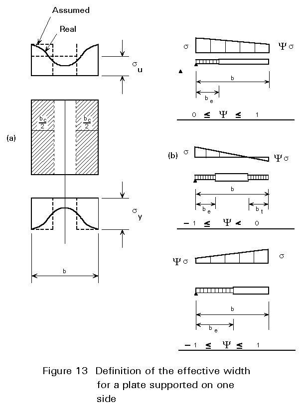
The stress distribution which is initially uniform, becomes non-uniform after buckling, since the central parts of the panel are not able to carry more stresses due to the bowing effect. The stress at the stiff edges (towards which the redistribution takes place) may reach the yield stress. The method is based on the assumption that the non-uniform stress distribution over the entire panel width may be substituted by a uniform one over a reduced "effective" width. This width is determined by equating the resultant forces:
b su = be sy (18)
and accordingly:
be = su.b/sy = kb (19)
which shows that the value of the effective width depends on the buckling curve adopted. For uniform compression the effective width is equally distributed along the two edges (Figure 13a). For non-uniform compression and other support conditions it is distributed according to rules given in the various regulations. Some examples of the distribution are shown in Figure 13b. The effective width may also be determined for values of s < su. In such cases
Equation (19) is still valid, but ![]() p, which is needed for the determination of the reduction factor k, is not given by Equation (16) but by the relationship:
p, which is needed for the determination of the reduction factor k, is not given by Equation (16) but by the relationship:
![]() p
= Ö(s/scr)
(20)
p
= Ö(s/scr)
(20)
The design of thin walled cross-sections is performed according to the following procedure:
For given actions conditions the stress distribution at the cross-section is determined. At each subpanel the critical stress scr, the relative slenderness
![]() p
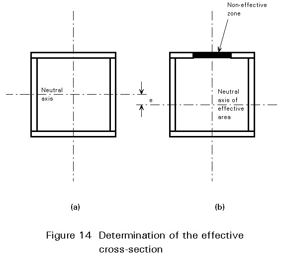
and the effective width be are determined according to Equations (7), (16) and (19), respectively. The effective width is then distributed along the panel as illustrated by the examples in Figure 13b. The verifications are finally based on the characteristic Ae, Ie, and We of the effective cross-section. For the cross- section of Figure 14b, which is subjected to normal forces and bending moments, the verification is expressed as:
p
and the effective width be are determined according to Equations (7), (16) and (19), respectively. The effective width is then distributed along the panel as illustrated by the examples in Figure 13b. The verifications are finally based on the characteristic Ae, Ie, and We of the effective cross-section. For the cross- section of Figure 14b, which is subjected to normal forces and bending moments, the verification is expressed as:
![]() (21)
(21)
where e is the shift in the centroid of the cross-section to the tension side and gm the partial safety factor of resistance.
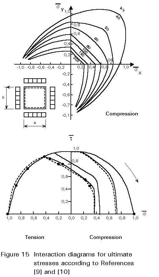
The effective width method has not been extended to panels subjected to combinations of stress. On the other hand the interaction formulae presented in Section 2.2 do not accurately describe the carrying resistance of the plate, since they are based on linear buckling theory and accordingly on elastic material behaviour. It has been found that these rules cannot be extended to cases of plastic behaviour. Some interaction curves, at the ultimate limit state, are illustrated in Figure 15, where all stresses are referred to the ultimate stresses for the case where each of them is acting alone. Relevant interaction formulae are included in some recent European Codes - see also [9,10].
Finite element methods
When using finite element methods to determine the ultimate resistance of an unstiffened plate one must consider the following aspects:
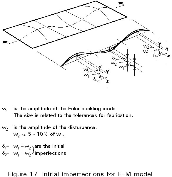
The first order Euler buckling mode can be used as a first approximation to this shape. In addition, a disturbance to the first order Euler buckling mode can be added to avoid snap-through problems while running the programme, see Figure 17. The amplitude of the initial imperfect shape should relate to the tolerances for flatness.
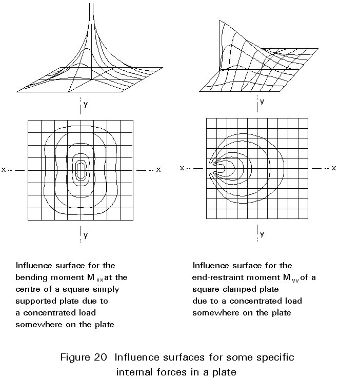
If the plate deformations are small compared to the thickness of the plate, the middle plane of the plate can be regarded as a neutral plane without membrane stresses. This assumption is similar to beam bending theory. The actions are held in equilibrium only by bending moments and shear forces. The stresses in an isotropic plate can be calculated in the elastic range by solving a fourth order partial differential equation, which describes equilibrium between actions and plate reactions normal to the middle plane of the plate, in terms of transverse deflections w due to bending.
Ñ
4w =where:
|
q = q(x, y) |
is the transverse loading |
|
D = Et3/12(1- |
is the stiffness of the plate having thickness t, modulus of elasticity E, and Poisson's ratio u . |
|
|
is the biharmonic operator |
In solving the plate equation the prescribed boundary (support) conditions must be taken into account. For example, for an edge parallel to the y axis, w = ¶w/¶n = 0 if the edge is clamped, or w = ¶w2/¶n2 = 0 if the edge is simply supported.
Some solutions for the isotropic plate are given in Figure 20.
An approximation may be obtained by modelling the plate as a grid and neglecting the twisting moments.
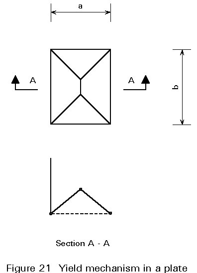
Plates in bending may react in the plastic range with a pattern of yield lines which, by analogy to the plastic hinge mechanism for beams, may form a plastic mechanism in the limit state (Figure 21). The position of the yield lines may be determined by minimum energy considerations.
If the plate deformations are of the order of the plate thickness or even larger, the membrane stresses in the plate can no longer be neglected in determining the plate reactions.
The membrane stresses occur if the middle surface of the plate is deformed to a curved shape. The deformed shape can be generated only by tension, compression and shear stains in the middle surface.
This behaviour can be illustrated by the deformed circular plate shown in Figure 22b. It is assumed that the line a c b (diameter d) does not change during deformation, so that a¢ c¢ b¢ is equal to the diameter d. The points which lie on the edge "akb" are now on a¢ k¢ b¢ , which must be on a smaller radius compared with the original one.
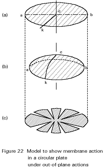
Therefore the distance akb becomes shorter, which means that membrane stresses exist in the ring fibres of the plate.
The distribution of membrane stresses can be visualised if the deformed shape is frozen.
It can only be flattened out if it is cut into a number of radial cuts, Figure 22c, the gaps representing the effects of membrane stresses; this explains why curved surfaces are much stiffer than flat surfaces and are very suitable for constructing elements such as cupolas for roofs, etc.
The stresses in the plate can be calculated with two fourth order coupled differential equations, in which an Airy-type stress function which describes the membrane state, has to be determined in addition to the unknown plate deformation.
In this case the problem is non-linear. The solution is far more complicated in comparison with the simple plate bending theory which neglects membrane effects.
The behaviour of the plate is governed by von Karman's Equations (13).
![]()
where F = F(x, y) is the Airy stress function.
More or less the same considerations hold when using FEM to determine the stress distribution in plates which are subject to out-of-plane action as when using FEM for plates under in-plane actions (see Section 2.1.3), except for the following:
Except for the yield line mechanism theory, all analytical methods for determining the stress distributions will also provide the deformations, provided that the stresses are in the elastic region.
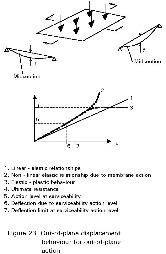
Using adequate finite element methods leads to accurate determination of the deflections which take into account the decrease in stiffness due to plasticity in certain regions of the plate. Most design codes contain limits to these deflections which have to be met at serviceability load levels (see Figure 23).
The resistance of plates, determined using the linear plate theory only, is normally much underestimated since the additional strength due to the membrane effect and the redistribution of forces due to plasticity is neglected.
An upper bound for the ultimate resistance can be found using the yield line theory.
More accurate results can be achieved using FEM. The FEM program should then include the options as described in Section 3.1.2.
Via an incremental procedure, the action level can increase from zero up to the desired design action level or even up to collapse (see Figure 23).
The out-of-plane action has an unfavourable effect on the stability of an unstiffened plate panel in those cases where the deformed shape due to the out- of-plane action is similar to the buckling collapse mode of the plate under in-plane action only.
The stability of a square plate panel, therefore, is highly influenced by the presence of out-of-plane (transversely directed) actions. Thus if the aspect ratio a is smaller than ![]() , the plate stability should be checked taking the out-of-plane actions into account. This can be done in a similar way as for a column under compression and transverse actions.
, the plate stability should be checked taking the out-of-plane actions into account. This can be done in a similar way as for a column under compression and transverse actions.
If the aspect ratio a is larger than ![]() the stability of the plate should be checked neglecting the out-of-plane actions component.
the stability of the plate should be checked neglecting the out-of-plane actions component.
For strength verification both actions have to be considered simultaneously.
When adequate Finite element Methods are used, the complete behaviour of the plate can be simulated taking the total action combination into account.
[1] Bryan, G. K., "On the Stability of a Plane Plate under Thrusts in its own Plane with Application on the "Buckling" of the Sides of a Ship". Math. Soc. Proc. 1891, 54.
[2] Szilard, R., "Theory and Analysis of Plates", Prentice-Hall, Englewood Cliffs, New Jersey, 1974.
[3] Brush, D. O. and Almroth, B. O., "Buckling of Bars, Plates and Shells", McGraw-Hill, New York, 1975.
[4] Wolmir, A. S., "Biegsame Platten und Schalen", VEB Verlag für Bauwesen, Berlin, 1962.
[5] Timoshenko, S., and Winowsky-Krieger, S., "Theory of Plates and Shells", Mc Graw Hill, 1959.
[6] Chwalla, E., "Uber dés Biégungsbeulung der Langsversteiften Platte und das Problem der Mindersteifigeit", Stahlbau 17, 84-88, 1944.
[7] Dubas, P., Gehri, E. (editors), "Behaviour and Design of Steel Plated Structures", ECCS, 1986.
[8] Eurocode 3: "Design of Steel Structures": ENV 1993-1-1: Part 1.1: General rules and rules for buildings, CEN, 1992.
[9] Harding, J. E., "Interaction of direct and shear stresses on Plate Panels" in Plated Structures, Stability and Strength". Narayanan (ed.), Applied Science Publishers, London, 1989.
[10] Linder, J., Habermann, W., "Zur mehrachsigen Beanspruchung beim"
Plattenbeulen. In Festschrift J. Scheer, TU Braunschweig, 1987.