ESDEP WG 15A
STRUCTURAL SYSTEMS: OFFSHORE
To describe the general methods of jacket fabrication. To discuss the various stages of operation from material selection, through erection, including construction practices and equipment. To indicate the calculations normally involved.
Lecture 15A.1: Offshore Structures: General Introduction
Lectures 3.1: General Fabrication of Steel Structures
Lectures 3.2: Erection
Lectures 3.3: Principles of Welding
Lectures 3.4: Welding Processes
Lectures 15: Structural Systems: Offshore
The construction philosophy and definition of the construction phases of the fabrication of offshore structures are described. The overall execution plan and the contractor's organisation for its implementation are introduced and constructability i.e. the more general aspects of design - the size and transportability of components, welding access considerations, construction tolerance, is discussed.
The fabrication of nodes and reinforced tubulars, including the fabrication procedure for a typical node is described together with jacket assembly and erection and the procedures for "big lift".
Jacket construction involves the following work phases:
Procurement
The technical and commercial activities required to supply material and specialised products to enable the execution of construction activities.
Fabrication
The processes normally carried out in a fabrication shop to produce relatively small units. Thus fabrication includes processes such as cutting, rolling, pressing, fitting, welding, stress relieving on such items as welded tubulars, beams, nodes, girders, cones, supports, clamps, etc.
Assembly
The processes normally performed outside the fabrication shop but at ground level in order to assemble groups of shop fabricated items into an (assembled) unit for subsequent erection in accordance with a construction sequence.
Erection
The processes required to install assembled and shop fabricated items together in their final configuration. These processes include fitting and welding. However the emphasis is on the transportation and lifting of heavy assemblies.
The design of a jacket, i.e. a lifted, launched or self-floating jacket, is determined primarily by the offshore installation equipment available and the intended water depth. In general the preference is to lift the jacket in place. The size of such jackets has being increasing as offshore lifting capacity has grown. With modern lifting capacity now up to 14,000 tonnes, jackets approaching this order of magnitude are now candidates for lifting into position.
For jackets destined for shallow water, where the height is of the same order as the plan dimensions, erection is usually carried out vertically, i.e. in the same attitude as the final installation. Such jackets may be lifted or skidded onto the barge.
Jackets destined for deeper water are usually erected on their side. Such jackets are loaded by skidding out onto a barge. Historically most large jackets have been barge launched. This method of construction usually involves additional flotation tanks and extensive pipework and valving to enable the legs to be flooded for ballasting the jacket into the vertical position on site. This method of construction is currently applicable for jackets up to 25,000 tonnes. Very large jackets, in excess of this, have been constructed as self-floaters in a graving dock and towed offshore subsequent to flooding the dock.
In considering the construction philosophy and contract strategy, the objectives of achieving quality requirements and efficiency are of fundamental importance. An offshore jacket goes through a series of very distinct stages as it moves from fabrication to load-out. These stages range from operations which are almost totally automatic under very controlled conditions, e.g. steel production, automatic welding, to operations which are almost totally manual in very variable conditions, e.g. yard erection, offshore activities. Thus decreasing efficiency occurs as progress through these operations advances. In addition, the stable conditions in repetitive processes of the early operations are more conducive to the maintenance of high quality. A third basic consideration is that risk increases with each progressive stage. These general trends during construction are shown in Table 1.
It is clear therefore that, as a general principle, as much work as possible should be undertaken in the earlier more productive, higher quality, less risky phases of the project.
Some of the principles which reduce the time and cost of construction are:
Quality management is a vital and integral component of all aspects of offshore fabrication. Essentially it involves ensuring that what is produced is what is needed. The requirements for documentation, hold point, audits, reviews and corrective actions are part of the quality assurance process. They are crucial tools for controlling the project execution and providing verifiable evidence of the fabricator's competence.
Quality control, inspection and testing should be performed during all phases of construction to ensure that specified requirements are being met. The most effective quality scheme is one which prevents the introduction of defective materials and workmanship into a structure, rather than finding problems after they occur.
A general note on Quality Assurance for Offshore Construction is included in Appendix 1. It is applicable to this lecture and also to Lecture 15A.9: Installation.
Engineering of execution, 'construction engineering', entails the work required during each phase of execution to ensure that the design requirements are fulfilled. A general method of execution is envisaged at the jacket design stage. Since the shape of the jacket, its form and properties require quite specific methods of load-out, offshore transportation and installation (which are construction activities executed under contractor responsibility), there is considerable interfacing of engineering requirements in these phases. In the earlier phases, i.e. procurement through assembly and erection, the contractor, while being limited by design specification requirements, has freedom of choice with regard to the exact method of execution adopted. However, in all phases the contractor is required to demonstrate that the methods which he adopts are compatible with the specification requirements and do not affect the integrity of the structure.
Each phase of execution has its own specific engineering requirements which are determined by the processes executed during that phase. These processes range from those which are largely repetitive early in execution to one-off activities in the latter phases. Accordingly the engineering which supports procurement and shop fabrication is voluminous but repetitive, e.g. material take-offs, shop drawings, cutting plans, etc. The assembly and erection phases are supported by a mix of repetitive engineering, e.g. scaffolding, and specific studies for limited series of activities.
The volume of contractor construction engineering on a large jacket is typically 130,000/150,000 hours. The typical organisation of a contractor's technical documents is shown in Table 2.
When designing larger components consideration must be given to their subdivision into elements which will not distort when fabricated and which can be relatively easily assembled without welding/dimensional problems. For instance, nodes are categorised as either complex or simple from the execution viewpoint based on the number of separate fitting-welding-NDT (non-destructive testing) cycles required during fabrication and the possibility of automatic welding between the node can and the tubular during sub-assembly. The number of fitting-welding-NDT cycles depends on the existence of ring stiffeners and the number and disposition of stubs. For reasons relating to weld distortion and to allow automatic welding, it is almost essential that ring stiffeners be installed prior to fitting/welding of stubs. This adds an extra cycle to the fabrication of the node. Thus ring stiffeners are best avoided. Where this is not possible, care should be taken to define them at an early stage on critical nodes.
Node stubs can be classified as simple or overlapping. Overlapping stubs add at least one complete cycle to node fabrication and should therefore be avoided where possible. The minimum separation between the weld toes of adjacent simple stubs is typically specified as 50mm, see API RP2A, Fig. 4.3.1-2 [1]. However this distance is too small to allow simultaneous welding of adjacent stubs - 150mm is a more practical distance.
The specifications for fabrication of offshore jackets are determined by the designer. They are usually based on one or more of the well known codes, with additional requirements dictated by the specific design, client standards, statutory rules, etc. Two recognised codes which are used extensively for establishing general requirements are the API RP2A Recommended Practice for Planning, Designing and Constructing Fixed Offshore Platforms, [1] and AISC Specification for the Design, Fabrication and Erection of Structural Steel for Buildings [2].
For larger jackets, the nodes tend to be fabricated separately under highly controlled shop conditions. Alternatively cast steel nodes may be used in order to eliminate critical welding details.
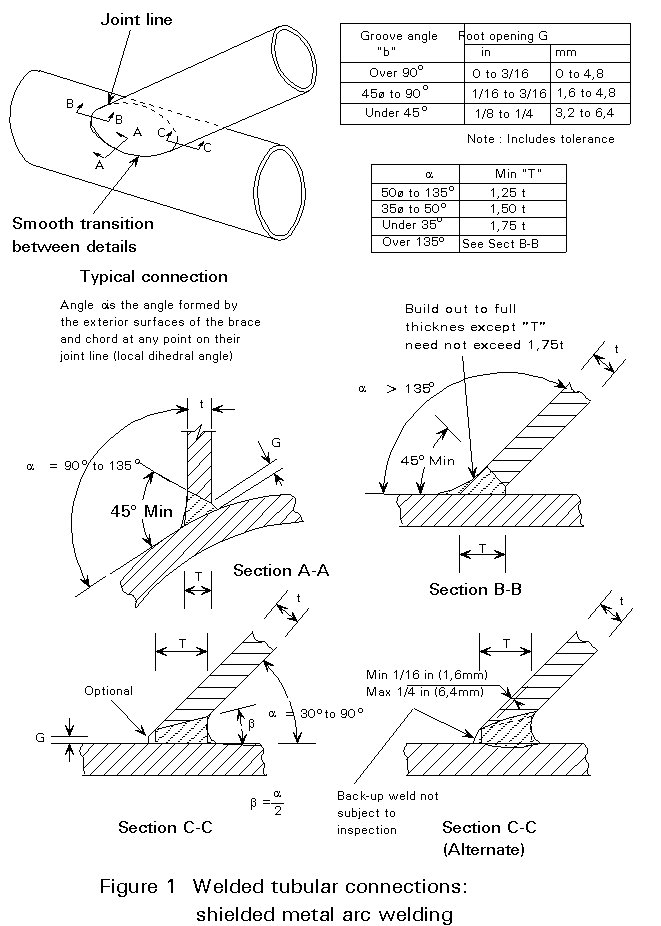
Recent experience, both in the laboratory and as a result of in-service inspection, has prompted increasingly greater attention to the welding aspects of fabrication. In particular greater attention has been focused on the importance of complete joint penetration groove welds, elimination of "notch effects" at the root and especially the cap of node welds, and achieving the required weld profile. Welds which are critical for fatigue endurance may be required to be ground to a smooth curve. This process reduces the probability of brittle failure. However it also implies increasingly sophisticated and stringent fabrication and quality assurance/quality control (QA/QC) requirements. Typical welding details from API RP2A [1], showing tubular members framing into or overlapping another member with access from one side only, are shown in Figure 1. However, a lot of emphasis is placed on designing stubs which can be welded from both sides. For instance, in the weld details for the Bouri jacket, Figure 2, most stubs are accessible from both sides.

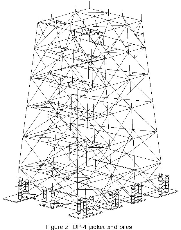
Welding procedures are required, detailing steel grades, joint design, welding consumables, etc. Welds are typically subject to 100% visual, magnetic particle inspection (MPI) and ultrasonic test (UT) inspection. The weld acceptance criteria, e.g. maximum weld undercut length (t/2 or 10mm), and maximum depth (t/20 or 0,25mm), imply an exceptionally high quality of welding. In addition all welders should be qualified for the type of work assigned to them and certified accordingly.
The location and orientation of circumferential and longitudinal welds during construction is based on minimising interferences and ensuring the minimum distance between circumferential welds. Special attention is required on items such as pile sleeve shear plates, launch runners, mudmats, etc. where planned avoidance of weld interference is critical.
All temporary plates and fittings should be subjected to the same requirements for weld testing as the member to which they are being affixed. There is also an overriding necessity to ensure that such attachments are located at a safe distance from main structural welds in order to minimise the risk of defect propagation. This is not unduly conservative - the "Alexander Kielland" capsized due to a fatigue crack initiated at the attachment of a sonar device to a principal structural member. Temporary cut-outs should be of sufficient size to allow sound replacement. Corners should be rounded to minimise stress concentrations.
Where welds are found to be defective, they should be rectified by grinding, machining or welding as required. Welds of insufficient strength, ductility or notch toughness should be completely removed prior to repair.
In general, sub-assemblies are executed so that at least one of the two edges which will mate during subsequent assembly/erection has a cut-off allowance. This procedure provides flexibility in that the sub-assemblies can be sent to the field with the cut-off allowance in place and cut to fit on location. Alternatively they can be cut to exact dimensions during sub-assembly where the as-built dimension has already been determined.
The primary structure nodes are frequently geometrically complex. Accordingly their fabrication presents particular problems, especially from the points of view of welding and dimensional control.
On a complex jacket the designer may specify the node cans, or the whole node including stubs and ring stiffeners, in material with specified through-thickness properties. This requirement is introduced because of tearing or punching effects likely to be sustained by these elements during their design life and indeed during fabrication. The designer may also "thicken" or reinforce the cans to withstand local stresses. Finally, in an effort to ensure that node welds contain minimal levels of residual stress due to fabrication, thermal stress relieving or post-weld heat treatment (PWHT) of the heavier more restrained welds may be prescribed. This is frequently a requirement for thicker walled North Sea jackets.
API RP2A [1] provides specific tolerances for final fabrication. The contractor must work within tolerances which preserve dimensional compatibility and observe weight control requirements at each phase of construction. Bearing these requirements in mind, node fabrication tolerances are tight, e.g. typical working points within 6mm of theoretical, stub angle within 1 minute, all braces within 12mm of the design dimension.
The typical fabrication process for a conventional node, assuming that the can (with or without ring stiffeners) has already been fabricated, commences with profiling of stubs and terminates with UT inspection of the finished node after PWHT.
The intermediate stages can be performed in several different ways, some of which depend on the specific geometry of the node and many of which depend on fabricator preference. Some fabricators prefer to orient the can upright, maintaining that it enables more stubs to be fitted simultaneously. However the majority of fabricators tend to fit the stubs to a can placed on horizontal rollers. The sequential steps in the fabrication of a typical node are as follows:
Sub-assembly can be considered as an intermediate stage between standard shop fabrication, i.e. nodes, tubulars, beams etc. and assembly or erection. The emphasis is on performing the maximum number of welds in the shop. This ensures the highest weld quality since many node and tubular welds can be double-sided and/or automatic when performed in the fabrication shop.
When defining sub-assemblies, the principal factors to be borne in mind are the following:
Of all the areas of quality control (QC) which require attention, that of dimensional control, as emphasised in the code and specifications, tends to be exaggerated. However, it is clear that attention must be paid to the dimensions which have structural significance, e.g. the straightness of elements, ovality of tubulars, eccentricities at node joints, etc. It is also clear that on a jacket the global alignment/verticality of items such as pile sleeves, conductor guides, launch runners, etc. are also important. Finally dimensional control of items which are intended for "mating" or "removal" offshore, for example piles/pile sleeves, jacket top/MSF base, buoyancy tank/supports, etc. is vital to the efficiency of offshore installation. There are therefore, many aspects where the attention to dimensional control is justified even if the overall design might occasionally benefit if the designer did not always require that everything fitted so tightly.
The principal reason for requiring such accurate dimensional control of nodes and tubulars during fabrication is not because of the structural consequences of out-of-tolerance but rather because the parts may not fit together in the yard. It is one of the most vexing incongruities of the tubular steel jacket concept that the theoretical tolerances on node stub eccentricity are generous from the structural viewpoint while the actual tolerances are very tight because of considerations regarding the fitting together of components during subsequent phases of construction.
The dimensional control of node fabrication, in particular, involves potentially intricate calculations in the shop. However, the most successful systems simply involve the inclusion on the shop drawings of several additional "checking" measurements and the correct marking of the node can and stub generators and offsets.
Shop fabricated sub-assemblies and loose items are incorporated into assemblies which constitute the major lifts of the erection sequence. Thus for a large jacket, the assemblies are typically of four types:
The assembly and erection phases are based on the following objectives:
The assembly of a jacket frame, often having a spread at the base of 50m or more, places severe demands on field layout and survey and on temporary support and adjustment bracing. Such large dimensions mean that the thermal changes can be significant. Temperature differences may be as great as 30°C between dawn and afternoon and as much as 15°C between various parts of the structure, resulting in several centimetres distortion. However, the practice of 'using the sun' to fit elements which are not dimensionally in-tolerance is common in the field. This procedure in itself tends to induce residual stresses in the structure. Because of the difficulty associated with thermal distortion, it is normal to "correct" all measurements to a standard temperature, e.g. 20° C.
Elastic deflections are also a source of difficulty in maintaining tolerances in the location of nodes. Foundation displacements under the skid beams and temporary erection skids must be carefully calculated and monitored.
The overall assembly sequence and programme requires that each assembly be completed prior to lifting. It is normal to determine the exact location, orientation and attitude, i.e. face-up or face-down, of each assembly in the field in anticipation of its lifting procedure.
Assembly layout drawings are usually prepared showing central co-ordinates for each assembly. The central co-ordinates are then used as local bench marks with the object of defining the assembly, the sub-assemblies, loose items, appurtenances and temporary attachments which comprise, field welds, overall dimensions, weight, reference drawings, etc.
Dimensional control of the assembly both prior to and after welding, can be by means of a series of self-checking measurements on the structure itself. Provided cross checks are adequate, the time consuming exercise of referring measurements to an external bench mark can be avoided.
Normally the assembly is tacked in position to theoretical dimensions using allowable positive tolerances to compensate for weld shrinkage. Perhaps the most fundamental rule in fitting is the avoidance of "force-fitting" of members prior to welding or to force stresses into unwelded members through the welding sequence since such conditions cannot have been foreseen by the designer.
An outline sequence of events which apply to all types of assembly is as follows:
In this phase assembled, sub-assembled and fabricated structures, together with loose items, are incorporated into the final structure according to the sequence outlined in Figure 3a - 3e.
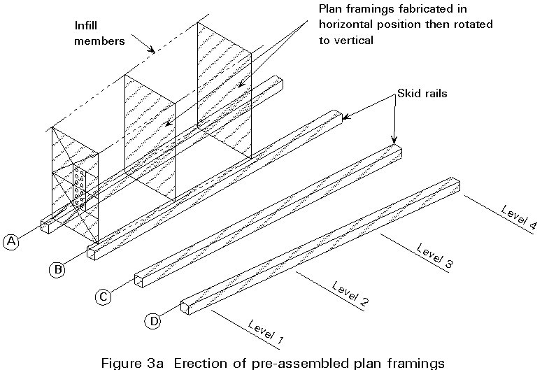


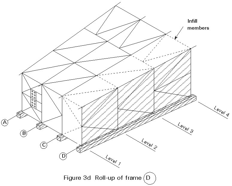
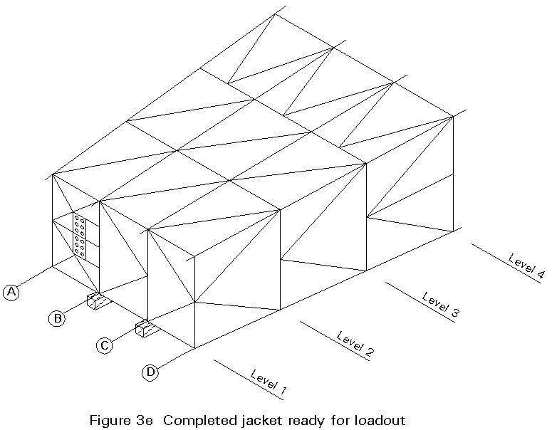
Jacket frames are typically laid out flat and then rolled using multiple crawler cranes. Co-ordinating such a rigging and lifting operation requires thoroughly developed three-dimensional layouts, firm and level foundations for the cranes and experienced, well rehearsed operators.
Twenty four cranes were involved in the two major side frame lifts during the erection of platform Cerveza, which was 300m long.
For the Magnus platform and Bouri DP3, a different procedure known as "toast rack" was used. Here the jacket horizontal levels were fabricated, erected in place and tied in to complete the jacket.
For the Bullwinkle jacket, one of the world's largest, sections of the jacket were fabricated in Japan, transported by barge to Texas and assembled using jacking towers which rolled up the sections to heights as great as 140m.
For jackets destined for shallow water erection is usually carried out vertically, i.e. in the same attitude as the final installation. Such jackets may be lifted onto the barge or skidded out. In this latter case, adequate temporary pads and braces must be provided under the columns to distribute the loads for skidding.
The structural analysis associated with the erection procedure for a given assembly usually involves a computer model with all relevant structural characteristics. The assembly is analysed for a number of load cases which correspond (approximately) to the support conditions of the assembly at its presumed critical attitudes, i.e. the locations of the cranes, bogies, saddles, etc. when the panel is being transported and when it is in horizontal and vertical attitudes. The structural analysis for lift/transport identifies the worst cases from the point of view of structural response. These cases are then analysed to determine the maximum stresses and displacements. The calculations should show that global and local stresses are within allowable limits according to API/AISC codes.
Frequently, a structural analysis computer programme is used for this purpose. The analysis will indicate where bending stresses are high and/or crane, bogie or support loads inadmissible. Thus modifications can be made to redistribute structural stresses and loads at "supports" to optimise both and ensure that neither the cranes nor the structure can be overloaded during erection.
An outline sequence for the erection of all major components would be:
Jacket structural completion is followed by a short phase during which all the jacket systems, both permanent and those required during installation, are completed and rendered functional. The load-out operations are covered in Lecture 15A.9: Installation.
[1] API RP2A, Recommended Practice for Planning, Designing and Construction of Fixed Offshore Installations, latest edition.
Engineering design principles and practices that have evolved during the development of offshore oil resources.
[2] AISC Specification for the Design, Fabrication and Erection of Structural Steel for Buildings, latest edition.
API code refers to this specification for calculations of basic allowable stresses of all jacket members.
[1] Det Norkse Veritas Marine Operations Recommended Practice RP5 - Lifting (June 1985).
Principles and good practice for offshore heavy lifts.
[2] AWS Structural Welding Code AWS D1.1-88.
All jacket welding and weld procedure qualifications are required by the API code to be undertaken in accordance with this code.
[3] Det Norske Veritas, Rules for the Design, Construction and Inspection of Offshore Structures, 1977.
Rules for construction and installation of steel jackets as required by DNV.
[4] Lloyd's Register of Shipping, Rules and Regulations for the Classification of Fixed Offshore Installations, 1989.
Based on Lloyd's experience from certification of over 500 platforms world-wide.
APPENDIX 1
Quality Assurance and Quality Control
It is becoming increasingly common for operators to specify that the quality of construction for offshore structures be controlled by a recognised quality system management standard.
ISO 9000/EN 29000, Standard for Quality Systems Management, is recognised as the accepted standard in such situations. These standards set down the requirements that a soundly based quality management system must fulfil if it is to assist in properly defining and controlling product quality. Because the standards deal with the quality system, and are not product standards, they are applicable to many sectors of industry including offshore construction. They apply in any situation where management wish to adopt a clearly defined policy and an orderly approach to providing a quality product.
All aspects of a company's activities are covered in the standards including:-
|
Design |
Product Traceability |
|
Contract Review |
Process Control |
|
Documentation Control |
Inspection/Testing |
|
Management Responsibility |
Calibration of Equipment |
|
Purchasing |
Control of Non-Conformances |
|
Corrective Action |
Handling/Storage/Delivery |
|
Quality Records |
Training |
|
Management Review/Audits |
Etc. |
QA Management Complexity
The overall programme for a jacket construction, shows that there are a very considerable number of offshore activities in many different locations within a very short period of time. The evaluation of the performance of such a range of activities and at a number of centres is a major QA/QC undertaking.
It is difficult to fully appreciate the scope of documentation on a jacket construction project. Consider the documentation which is expected to flow from one location to another in respect to a single node. From the time the plate is manufactured until it is located in the final structure, a dossier must be compiled. This documentation could commence with copies of certificates from the steel plate manufacturer and progress through several welding, NDT, dimensional control phases at a number of successive locations, culminating in the issue of a Release Note at the node fabrication shop.
Clearly this is necessary on some items, e.g. steel, welds, NDT Certificates for the jacket primary structure, risers, etc. These documents may be useful during maintenance of the platform enabling many in-service problems to be traced to abnormalities which occurred during construction. Construction of a large jacket typically involves thousands of steel plates. Each plate inevitably becomes an individual as it is allocated a unique number corresponding to a Material Utilisation Schedule or Cutting Plan. The individual number of pieces of plate could be in excess of 20,000 items. The primary object of material control is to ensure that, at any stage of construction, the origin of each and every item can be traced back to a material certificate which in turn corresponds to a set of test/chemical composition etc. as contained in the Data Dossier. However, voluminous as this documentation may be, it constitutes less than half of the total documentation produced for a complete jacket. Consider for instance the number of welds in a complex buoyancy tank, the walkways on top of the jacket, the anodes, launch runners, grout lines, etc. Each of these must be welded, several must be individually inspected. However the requirement to produce sophisticated documentation in respect of each is questionable. For this reason it is important that agreement is reached at an early stage as to the individual items which require identification, that these be kept to a minimum and that the identification system be simple. In actual practice it has proven to be very difficult to make all materials really traceable. Much more could be done to structure such documentation in such a way that it would really be of help throughout the platform life.
Procedures and Specifications
Within the Contractor's organisation QA/QC procedures must be developed for the project, many of which will be specifically for jacket construction. These are divided into Management Procedures (e.g. Management of Non Conformities, Management of Jacket Completion Onshore, etc.) and Control Procedures (e.g. Procedure for Ultrasonic Testing of welds at Jacket Yard, Dimensional Control Procedure for Node Fabrication at factory etc.). Construction Procedures/Specifications are also required (e.g. Jacket Assembly and Erection Procedure, Pile Installation Procedure, etc.) in addition to a vast number of weld procedure specifications and qualifications, welder qualifications and inspection plans.
Even if the number of specific procedures required from each subcontractor is minimised, a fabrication subcontractor will still be required to develop procedure and specifications for the following typical functions/activities: subcontract organisation, material control, fabrication method/sequence, procedures for cutting, forming, pre-heating, post-weld heat treatment along with the more obvious welding and NDT procedures and Inspection Plans. Typically hundreds of procedures/specifications must be developed by jacket subcontractors.
Certification
On most offshore projects, the underwriters normally agree to insure the plant during its operating life provided it is designed, constructed and maintained to predetermined standards and certified as such. This certification is also almost invariably required by the state authorities in whose waters the plant is installed. It is normally performed by one of the traditional ship classification societies known as the Certifying Authority (CA). In the widest sense, certification requires that the CA carry out independent surveillance to ensure that the standards chosen for the project are satisfactory and that the project is performed in accordance with them. Formerly this meant that the CA inspected every activity likely to influence the adequacy of the final product - an enormous task. More recently with the advent of QA, the certification function can mean audits of the construction so that, rather than inspect everything, the CA satisfies himself that the manner in which the construction is being managed and performed (based on incomplete but comprehensive inspection) is likely to lead to a satisfactory product.
|
Phase |
Work Centre |
Efficiency |
Quality Variability |
Risk |
|
Engineering |
Office |
Decreasing |
Increasing |
Increasing |
|
Procurement |
Factory |
Decreasing |
Increasing |
Increasing |
|
Fabrication |
Fabrication Shop |
Decreasing |
Increasing |
Increasing |
|
Assembly and Erection |
Yard Site |
Decreasing |
Increasing |
Increasing |
|
Loadout and Seafastening |
Transition |
Decreasing |
Increasing |
Increasing |
|
Transport and Installation |
Offshore Site |
Decreasing |
Increasing |
Increasing |
Table 1 Jacket Construction Phases and Characteristics
|
No. |
Document Series |
Group or Individual Subject Title |
|
1 |
Shop Drawings, Cutting Plan |
Welding standards, nodes, tubulars, piles, pile sleeves, clusters, conductor guide frames, launch runners, buoyancy tanks, cathodic protection system, protective coating systems, risers, j-tubes, caissons, boat landings, boat bumpers, walkways, grouting systems, ballasting system, installation aids, as-built drawings. |
|
2 |
Method and Temporary Works Drawings |
Subassemblies, assemblies, supports, access, scaffolding, lifting and transportation onshore, test and commission, identification. Onshore construction accessories. Offshore installation (preparation, transportation, lifting, launching, anchor patterns etc.). Offshore installation accessories (tools, guides, access, handling etc.). |
|
3 |
Quality Assurance Procedures |
Documentation identification, distribution and approval, witness and hold points, technical modifications and non-conformance management, material control, material identification and traceability, procurement and subcontracting, weld parameter control, management of specific problem areas. |
|
4 |
Quality Control Procedures |
NDT methods (visual, UT, x-ray, dye penetrant, MPI), dimensional control, destructive testing methods, NDT operator training and qualification, calibration of inspection equipment, pressure testing, miscellaneous testing. |
|
5 |
Manuals |
Testing, commissioning and preparation of jacket for tow. Load-out manuals - jacket piles, topsides. Installation manuals - jacket, piles, topsides. |
|
6 |
Weld Procedures |
For each location - weld procedures - repair procedures. |
|
7 |
Design Reports, Reviews and Specifications |
Quay design, skidway design, mooring system design, soil improvement spec., skidding system spec., dredging spec., transportation of jacket and piles, buoyancy tanks, jacket launching and emplacement, on-bottom stability, pile driveability, jacket levelling study. |
|
8 |
Engineering Meetings |
Normally held at critical phases of construction at the various construction locations. |
|
9 |
Fabrication, Assembly and Erection |
Fabrication/welding sequence (for principal items), forming, bending, stress relieving, coating, assembly and erection, temporary and secondary attachments, lifting and transporting, jackdown, weight control, settlement control, jacket weighing. |
|
10 |
Inspection plan |
Steel supply (at each supplier). Fabrication of typical jacket and pile components (at relevant centres). Assembly and erection. |
|
11 |
Technical Proposals and Non-Conformance Resolutions |
Technical Clarification Requests ) Technical Relaxation Requests ) Possible at every Major Non-Conformance Reports ) Phase of location Minor Non-Conformance Reports ) of the Project. |
Table 2 Jacket Construction Engineering:
Typical Organisation of Contractor's Technical Documents