ESDEP WG 17
SEISMIC DESIGN
To give, by means of earthquake damage studies, an overall view of the principal forms of seismic damage, together with some explanation of failure mechanisms.
None.
None.
It is not possible to design seismic resistant structures efficiently without understanding the ways in which they are damaged by earthquakes in practice. The design process is not simply a matter of analysis, calculation and following codes. A practical knowledge of building behaviour in earthquakes is essential.
Based on earthquake damage studies the principal forms of damage are described, together with some explanation of the mechanics of failures.
The slides presented are not limited to structural steelwork buildings for two reasons. The first is that many of the problems caused by earthquakes are common to all forms of construction. The second reason is that it is very hard to find pictures of steel buildings which have suffered serious damage in an earthquake!
Engineers are generally accustomed to static loads acting on elastic structures. One of the most important lessons learned from damage surveys is the difference in failure patterns between static loads applied in a single direction and those due to cyclic loading. Another lesson is the necessity in earthquake design to consider the behaviour of the main structural system after yielding.
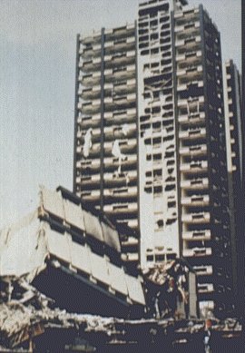
SLIDE 1 The Pino Suarez building in Mexico City was a 21-storey structural steel framed building constructed in about 1978. It suffered partial collapse and severe damage. Note the "K" bracings which rely on the compressive strength of members - a system without the ductility to absorb damage without collapsing.
An important aspect of post-earthquake study is the realisation of the important role that the quality of construction plays. Earthquakes do not respect theories, calculations or divisions of responsibility. Many instances of poor quality construction are invariably exposed in earthquake damaged buildings. Badly placed reinforcement, poorly compacted concrete, incomplete grouting of masonry and loose or missing bolts in structural steelwork are some of the commonest examples of poor quality.
Although the prime objective in the design of earthquake resistant buildings is the safety of the occupants and passers by, every earthquake shows up numerous examples of lives at risk from minor faults in construction - falling masonry or cladding, ceiling tiles dislodged, window frames separating from the walls and toppling inwards or outwards, and escape paths blocked by jammed doors and fallen masonry. Usually these types of failure could have been avoided with very little expense.
An important category of building failure in earthquake is the case where the building is so badly damaged that it has to be demolished, although it has not collapsed. For the owner and the insurance company the costs are similar whether the building collapses or is demolished. For the occupants it is the difference between life and death.
Where two buildings are close together, or where there is a movement joint in a building, the two sides are very likely to pound against each other during an earthquake. Major structural damage can result, particularly where the floor levels differ. The cause lies in the closeness of the two structures and in the flexibility of the buildings, factors which are within the control of the designer.
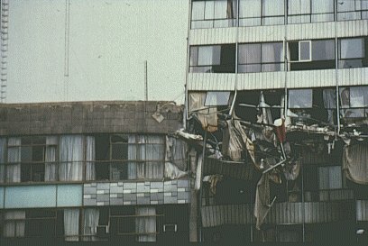
SLIDE 2 Adjacent buildings will pound against each other unless a sufficient space is allowed between them. In this case in Mexico City the failure of a complete storey has been brought about by the two buildings of differing height and dynamic properties pounding against each other.
Modern buildings are often assembled from many separate components. Older ones commonly have timber floors with joists poorly tied to the supporting walls. Any lack of tying together in a building is quickly exposed by seismic (earthquake) action. The nature of seismic ground motion inevitably leads to differential movement between separate components, and in the absence of structural continuity, differential movement will occur.
Aftershocks, generally of much smaller magnitude than the main seismic shock which they follow, play no explicit part in the design process. Nevertheless they play a significant part in the immediate post-earthquake rescue and survival operation. The further damage caused by aftershocks to already damaged buildings is greater than their magnitude would otherwise suggest. Following major earthquakes many structures brought to the brink of collapse by the main shock are destroyed by subsequent lesser shocks.
Concentrations of force occur where there are abrupt changes in structural stiffness or mass distribution. For this reason building form should be regular and symmetrical as far as the functional requirements permit.
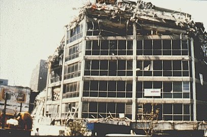
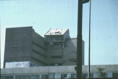
SLIDE 3 Although the storey shear is normally greatest for the base storey, variations in the strength, mass and stiffness can lead to failure initiating at any level - in this case a 'top down' failure in Mexico City.
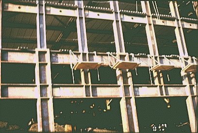
SLIDE 4 Finally some steelwork (undamaged) under construction in Los Angeles - an area of high seismicity. This welded frame has to cope with the functional requirement of the building owner that there should be fewer columns at the lowest storey for architectural reasons. This requirement is common in hotels and office buildings where more open space is needed at this level.
The effects of violent shaking on the ground are to increase lateral and vertical forces temporarily, to disturb the intergranular stability of non-cohesive soils, and to impose strains directly on surface material where the fault plane reaches the surface. A transient increase in lateral and vertical forces places any soil structures capable of movement at risk. The resulting types of damage are landslips and avalanches. Experience of the 1970 earthquake in Peru and the 1964 earthquake in Anchorage, Alaska, show that this damage may be on a massive scale. One village, Yungay, in Peru was destroyed almost entirely with the loss of 18,000 lives by a debris flow involving tens of millions of tons of rock and ice.
The disturbance of the granular structure of soils by shaking leads to consolidation of both dry and saturated material, due to the closer packing of grains. For saturated sands, pore pressure may be increased by shaking to the point where it exceeds the confining soil pressure, resulting in temporary liquefaction. This is an important effect. It can lead to massive foundation failure in bearing and piled foundations, the collapse of slopes, embankments and dams. It can cause the phenomenon of "boiling" where liquefied sand flows upwards in surface pockets. It is also possible for some unstable soils to heave.
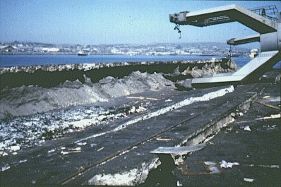
SLIDE 5 Serious ground failure may occur, especially in granular soils which are saturated. In this case the soil failure caused the collapse of a number of dockside cranes at Vina del Mar in Chile.

SLIDE 6 This building in Mexico City has suffered an overturning foundation failure, most probably initiated by failure of the supporting ground.
SLIDE 7 Settlement of foundations due to liquefaction or consolidation of the supporting soil can occur. In this Mexico City building almost the whole of the ground floor storey has vanished below street level. It is interesting to note that the building has not suffered a total collapse despite this settlement.
Shear movements in the ground may be at the surface or entirely below it. Where the earthquake fault reaches the surface, permanent movements of considerable magnitude, in metres rather than centimetres, may occur. Surface shear movements may also take place as a result of other soil displacement - landslips or consolidation for example. Sub-surface shear movements can occur in weaker strata, leading to damage of embedded or buried structures. Sub-surface shear movements also reduce the transmission of ground motion to the surface, effectively putting an upper bound on the surface motion.
In considering the more spectacular permanent ground displacements that can result from ground shaking, it should not be forgotten that elastic displacements also occur. They are critical in the design of piles, underground pipelines and culvert-type structures. Failures in underground piping and ductwork are common in earthquakes and have important implications for the post-earthquake emergency services.
The nature of ground shaking is substantially influenced by the subsoil underlying the site. Soft soils tend to vibrate at a lower frequency than hard ground sites but are likely to have a higher peak acceleration.
General indications of the effect of soil on the fundamental period of surface motion can be seen from Figure 1. The importance of the period in practice is the increased liability of damage where the natural period of the building is close to that of the ground. For low amplitude shaking, quite large amplifications are possible. In very soft soil, for example, amplifications of over 20 have been recorded for San Francisco Bay mud. However this effect is swiftly overcome by yielding of soft soils as amplitudes increase, so that, for strong shaking, peak accelerations are normally reduced in transmission through the upper levels of soil.

Considering the subsoil layers as a dynamic system, it is clear that surface responses will be modified if another structure is added at the upper level. The interaction of the structure and its supporting soil falls into two categories. Buildings in general are light in relation to the mass of the supporting soil and relatively flexible. Thus the addition of the building does not affect the surface ground motion significantly. However local flexibility of the soil where it is in contact with the foundation can modify the building response. The effects of this local flexibility are to modify vibration modes, lower natural frequencies and generate additional damping through energy dissipation in the surrounding soil. Although an increase in response can occur, the general effect is to produce a reduction in base shear. Piled foundations, in comparison with bearing foundations, generally have a lesser effect on the mode shapes and frequencies but produce lower damping effects.
The second type of soil structure interaction to be considered is where a structure is massive and rigid. In this case the structure becomes a significant element in the dynamic system represented by the subsoil and the structure. It causes the surface ground motion in its vicinity to be modified.
Failures of building foundations in earthquakes are not uncommon but are nearly always caused by failure of the supporting soil. Overturning failures due to uplift occur rarely, far less often than calculations would suggest. This rarity is probably due to the effective reduction in stiffness that accompanies uplift, which correspondingly reduces the force exerted by the ground acceleration. There can be no doubt that substantial tension from overturning forces can develop at foundation level. Examination of some lower failed columns in Caracas, following the 1967 earthquake, showed that they had failed in tension due to a combination of overturning forces and vertical ground acceleration.
Instances of failure in piles have been reported. In general, piles tend to conform with ground displacements and are vulnerable at points where adjacent strata have markedly different properties. Some configurations incorporating raked piles have failed at the underside of the pile cap.
Generally steel framed structures are engineered structures competent to resist gravity and wind loads. In the familiar processes of design, attention is commonly given to stresses before considering displacement. The secondary effects of displacement are often forgotten. Earthquake damage frequently draws attention back both to the direct effects of large displacements, such as the pounding at joints and damage to non-structural components and contents, and to the second order effects caused by large displacements.
Buildings with shear walls or braced frames, as long as they maintain their integrity, compare favourably in performance with more flexible framed structures as far a damage to contents and non-structural items is concerned. Particular points commonly revealed for framed structures are:
i. Corner columns often behave badly in comparison with other exterior and interior columns. This behaviour suggests that the effects of earthquake forces in orthogonal directions are not adequately dealt with in design.
ii. Complete failure in members detailed for ductility is rare. Where members with low ductility have failed it is clear that failure is swift. This behaviour is particularly marked in reinforced concrete members.
iii. The maximum practicable redundancy is shown to be desirable. The failure mechanism should involve as many members as possible, providing alternative load paths when one member yields or fails.
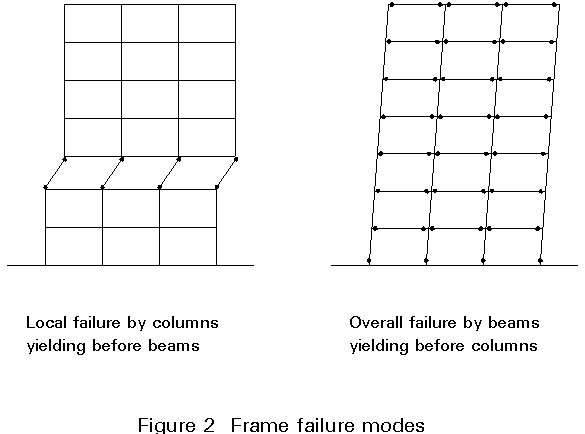
iv. Where yielding occurs in the columns before the beams, failure of the frame becomes much more likely. This point is illustrated in Figure 2 which shows the number of ductile hinges needed for failure in the column yielding mode compared with the beam yielding mode.
Structural steelwork shows the following types of damage from earthquakes:
i. Brittle failure of bolts in shear or tension.
ii. Brittle failure of welds, particularly fillet welds, in shear or tension.
iii. Member buckling, including torsional buckling.
iv. Local web and flange buckling.
v. Uplift of braced frames.
v. Local failure of connection elements such as cleats and tees.
vii. Bolt slip.
viii. High deflections in unbraced frames.
ix. Failure of connections between steel members and other building elements, such as floors.
x. Anchorages of components into masonry or concrete by cast in or expanding head bolts are almost invariably brittle in shear and tension. Thus they are unable to accommodate any movement. Accordingly failures are commonplace, aggravated when the masonry or concrete into which the anchorage is placed is also damaged.
xi. Many failures occur in horizontal torsion, especially in structures where the centres of mass and resistance are some distance apart on plan, or where the inherent torsional resistance of the system is low. A common case of a torsionally vulnerable structure is where buildings are located at street corners.
SLIDE 8 This Mexico City building experienced failure of ground floor columns due to a soft first storey and horizontal torsional effects.
Floor slabs function as diaphragms in transferring lateral forces. Figure3 shows two possible floor plans. In the first case there is very little diaphragm action but, in the second it is clearly significant. The transfer of shear at each end wall imposed high stresses in the slab. Some fully or partially prefabricated floor systems have very little strength in horizontal shear or bending.

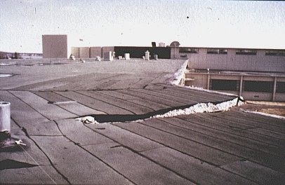
SLIDE 9 Horizontal diaphragms are not always rigid elements capable of distributing forces between frames. In this Anchorage school a reinforced concrete roof slab has torn like a piece of cardboard.
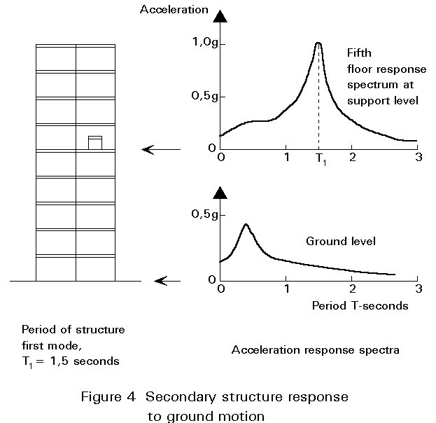
Appendages to buildings - masonry parapets, penthouses, roof tanks, cladding and cantilevers - tend to behave badly in earthquakes. The reasons for this are twofold. Firstly many of them are designed without any ductility, and secondly the effects of dynamic amplification by the building to which they are attached may greatly increase the forces applied to them.
Figure 4 illustrates the effect of the dynamic response of the building on the response spectrum, comparing the ground level spectrum with that at the fifth floor. The peak values are both amplified and shifted in frequency.
The contents of buildings often suffer major damage even when the building itself is relatively unharmed. This effect is greater for more flexible buildings. It represents an additional reason for the designer to exercise close control over displacements. In many modern buildings the contents are of greater value and importance than the building itself. The costs of preventing damage are often trivial, for example, use of steel angle ties to the tops of racks and floor bolts to shelving.
At any level in a multi-storey building the ground motion will be modified by the motion of the building itself. Generally the effect is to concentrate the frequency of response around a band close to the natural frequency of the building, and to amplify the peak acceleration roughly in proportion to the height, reaching an amplification of perhaps two or three at roof level.
Any contents which are either very stiff or which have a natural frequency of their own close to that of the building are therefore subjected to greater forces than they would experience if mounted at ground level.
Experience shows that non-structural items which are suspended such as ceiling systems and light fittings perform badly. Appendages such as parapets and mechanical plant also suffer high levels of damage, especially where they function as single degree of freedom "inverted pendulums". Damage also increases in multi-storey structures towards the roof. Roof tanks and penthouses are also subject to high forces.
SLIDE 10 All these cladding panels have fallen during the earthquake in Vino del Mar, Chile, creating a serious hazard for any occupants running for safety from the building. Cladding needs to be attached with ductile fixings capable of substantial deformation without fracture.
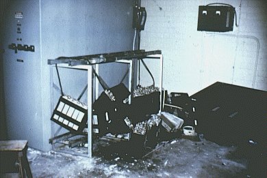
SLIDE 11 These batteries formed part of the emergency power system in a California hospital in 1972. During an earthquake the batteries fell off their racks and did not function when they were needed. Patients on life support systems died as a result. The contents of buildings are often of great value or importance and can be protected by limiting displacements and by simple cheap measures. In this case the batteries could have been strapped down or clipped to the racks which should have been bolted to the floor.
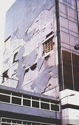
SLIDE 12 Surface finishes also present a major hazard when they fall, as in the case of this Mexico City building.
SLIDE 13 Experience with appendages to buildings such as this Mexico City water tank are that they perform badly in earthquakes. Dynamic response analysis also supports this experience. There is in effect a major discontinuity at the junction of the building and the tank with a resultant high stress concentration.

SLIDE 14 This Mexico City building illustrates the fragility of curtain wall glazing systems. They were unable to cope with the differential movement of the floors to which they were attached.
Failure of unreinforced masonry is so common that it is almost taken for granted and forgotten. Many earthquake codes ban the use of unreinforced masonry altogether. However, economic reasons still ensure that it is very widely used both for low-rise structural walls and as infill to framed structures.
Failures of both reinforced and unreinforced masonry in-plane are common. Masonry is very stiff and brittle in-plane so that the forces transmitted by ground shaking are high and failure is accompanied by a marked reduction in strength and stiffness. Damage normally comprises either collapse or diagonal cracking in both directions ("X" cracking). Cracks will often be concentrated around openings. Cracking will frequently follow the mortar joints.
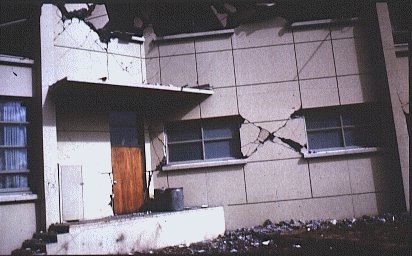
SLIDE 15 Typical `X' cracking of masonry in this Anchorage, Alaska school illustrates the effect of reversing horizontal shear forces during the earthquake. Shear stresses are concentrated opposite the window openings.
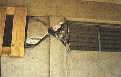
SLIDE 16 Where masonry buts up against a structural column it has the effect of concentrating shear over a short length so that the member can fail in shear (brittle failure) instead of bending (ductile failure). This behaviour is generally referred to as the short column effect.
The full implications of frame-infill masonry behaviour are complex. The failure of walls out-of-plane is common and causes substantial secondary damage.
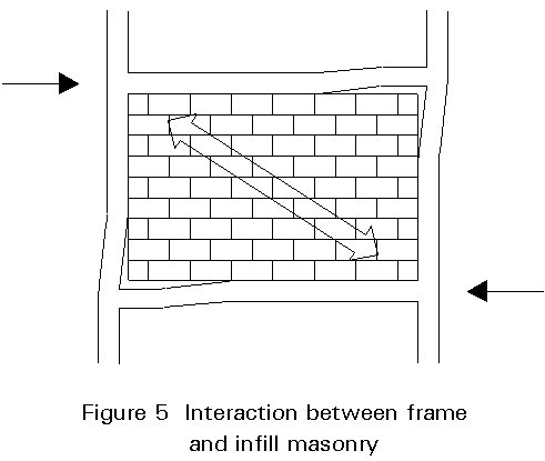
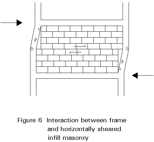
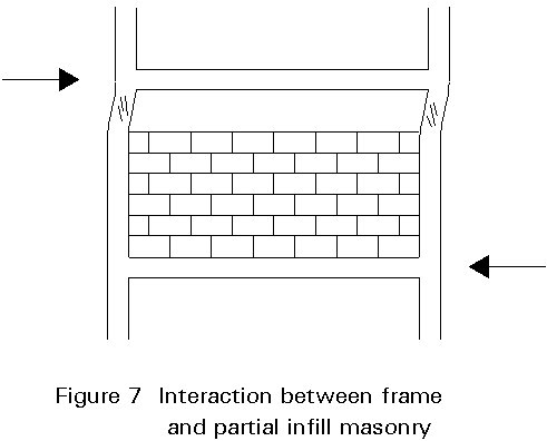
Figures 5 to 7 illustrate the interaction of infill masonry and frame in the in-plane direction. Figure 5 shows the interaction of the undamaged masonry panel with the frame. The masonry acts as a diagonal compression brace in the direction of the arrow, resulting in a substantial stiffening of the frame and redistribution of bending moments and shears in the frame. Figure 6 shows the effect of the horizontally sheared panel and accompanying rearrangement of the frame forces. Once the panel has sheared the effect of the diagonal compression zone is lost. Figure 7 shows the situation where the masonry does not occupy the whole of the panel, resulting in high shear forces in the unsupported portion of the column.
The redistribution in plan of forces, due to the stiffening effect of the infill masonry, is also of consequence. The frame may be stiffened leading to higher dynamic forces and accidental eccentricity leading to high torsional forces may result.
Some elements can be damaged by drift, or inter-storey displacement. Windows and cladding elements are frequently connected rigidly to more than one level and, if there is no ductile provision for relative movement in the connections, they may fail.
Steel tank structures are a specialised area dealt with in Lecture 17.6. They suffer from compression failure in the tank wall (including "elephant's foot" buckling) and tearing of the wall-floor joint.