ESDEP WG 15
STRUCTURAL SYSTEMS: MISCELLANEOUS
The lecture describes the basic principles used in the design of tanks for the storage of oil or water. It covers the design of vertical cylindrical tanks, and reference is made to the British Standard BS 2654 [1] and to the American Petroleum Industry Standard API650 [2].
None.
Lecture 8.6: Introduction to Shell Structures
Lecture 8.8: Design of Unstiffened Cylinders
Welded cylindrical tanks are commonly used to store oil products or water.
The principal structural element of these tanks is a vertical steel cylinder, or shell, which is made by welding together a series of rectangular plates and which restrains the hydrostatic pressures by hoop tension forces. The tank is normally provided with a flat steel plated bottom which sits on a prepared foundation, and with a fixed roof attached to the top of the shell wall.
This lecture explains the design basis for the structural elements of cylindrical tanks and illustrates the arrangements and the key details involved.
Oil and oil products are most commonly stored in cylindrical steel tanks at atmospheric pressure or at low pressure. The tanks are flat bottomed and are provided with a roof which is of conical or domed shape.
Water is also sometimes stored in cylindrical steel tanks. When used to store potable water they are of a size suitable to act as a service reservoir for a local community; they have a roof to prevent contamination of the water. Cylindrical tanks are also used in sewage treatment works for settlement and holding tanks; they are usually without a roof.
The sizes of cylindrical tanks range from a modest 3m diameter up to about 100m diameter, and up to 25m in height. They consist of three principal structural elements - bottom, shell and roof.
For petroleum storage, the bottom is formed of steel sheets, laid on a prepared base. Some tanks for water storage use a reinforced concrete slab as the base of the tank, instead of steel sheets.
The shell, or cylindrical wall, is made up of steel sheets and is largely unstiffened.
The roof of the tank is usually fixed to the top of the shell, though floating roofs are provided in some circumstances. A fixed roof may be self supporting or partially supported through membrane action, though generally the roof plate is supported on radial beams or trusses.
Clearly, common standards are generally applicable whether a tank holds oil or water, though it is the petroleum industry which has been responsible for the development of many of the design procedures and standards.
The two standards applied most widely are British Standard BS 2654 [1] and the American Petroleum Institute Standard API 650 [2]. These two Standards have much in common, although there are some significant differences (see Appendix A). Other standards, American and European, are not applied much outside their respective countries.
This lecture will generally follow the requirements of BS 2654 [1]. This standard is both a design code and a construction specification. The design code is based on allowable stress principles, not on a limit state basis.
Tanks designed for storage at nominally atmospheric pressure must be suitable for modest internal vacuum (negative pressure). Tanks may also be designed to work at relatively small positive internal pressures (up to 56 mbar (5,6 kN/m2), according to BS2654.
Non-refrigerated tanks are designed for a minimum metal temperature which is based on the lowest ambient air temperature (typically, ambient plus 10oC) or the lowest temperature of the contents, whichever is the lower. No maximum service temperature is normally specified.
Tanks are usually manufactured from plain carbon steel plate (traditionally referred to as mild steel) of grades S235 or S275 (to EN 10 025 [3]), or equivalent. Such material is readily weldable. The use of higher strength grades of low alloy steel (e.g. Grade S355) is less common, though its use is developing.
Notch ductility at the lowest service temperature is obtained for thicker materials (> 13 mm) by specifying minimum requirements for impact tests. This is normally achieved by specifying an appropriate sub-grade to EN 10 025 [3].
Internally, oil tanks are normally unpainted. Water tanks may be given a coating (provided it is suitably inert, where the water is potable), or may be given cathodic protection. Externally, tanks are normally protected. Where any steel is used uncoated, an allowance must be made in the design for loss of thickness due to corrosion.
A tank is designed for the most severe combination of the various possible loadings.
The dead load is that due to the weight of all the parts of the tank.
A minimum superimposed load of 1,2 kN/m2 (over the horizontal projected area) is applied to the roof of the tank. This load is commonly known as the 'snow load', but in fact represents, as well as a nominal snow load, any other imposed loads, such as maintenance equipment, which might be applied to the roof, and it includes the internal vacuum load. It is therefore applicable even in locations where snow is not experienced.
Non-pressure tanks are often fitted with valves which do not open until the vacuum reaches a value of 2,5 mbar, to contain vapour losses. By the time a valve is fully open, a vacuum of 5 mbar (0,5 kN/m2) may have developed. Even without valves a tank should be designed for a vacuum of 5 mbar, to cater for differential pressure under wind loads. In pressure tanks the valves may be set to 6 mbar vacuum, in which case a pressure difference of 8,5 mbar (0,85 kN/m2) may develop.
Actual predicted snow load or other superimposed load, plus appropriate vacuum pressure, should be used when it is greater than the specified minimum.
The weight and hydrostatic pressure of the contents, up to the full capacity of the tank, should be applied. Full capacity is usually determined by an overflow near the top of the tank; for a tank without any overflow, the contents should be taken to fill the tank to the top of the shell.
For oil and oil products, the relative density of the contents is less than 1.0, but tanks for such liquids are normally tested by filling with water. A density of 1000 kg/m3 should therefore be taken as a minimum.
Wind loads are determined on the basis of a design wind speed. Maximum wind speed depends on the area in which the tank is to be built; typically a value of 45 m/s is taken as the design wind speed, representing the maximum 3-second gust speed which is exceeded, on average, only once every 50 years.
In some areas, a tank must be designed to withstand seismic loads. Whilst some guidance is given in BS 2654 [1] and API650 [2] on the design of the tank, specialised knowledge should be applied in determining seismic loads.
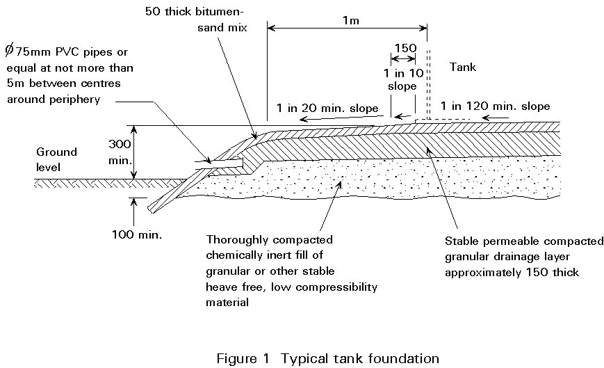
For petroleum storage tanks, steel bottom plates are specified, laid and fully supported on a prepared foundation.
The steel plates are directly supported on a bitumen-sand layer on top of a foundation, usually of compacted fill or, if the subsoil is weak, possibly a reinforced concrete raft. A typical foundation pad is shown in Figure 1 and a detailed description of the formation of this example is given in Appendix A of BS 2654 [1].
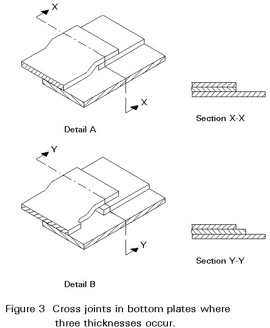
The bottom is made up of a number of rectangular plates, surrounded by a set of shaped plates, called sketch plates, to give a circular shape, as shown in Figure 2. The plates slightly overlap each other and are pressed locally at the corners where three plates meet (see Figure 3). Lapped and fillet welded joints are preferred to butt welded joints (which must be welded onto a backing strip below the joint) because they are easier and cheaper to make.

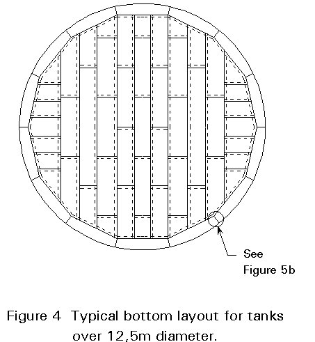
For larger tanks (over 12,5 m diameter, according to BS 2654) a ring of annular plates is provided around the group of rectangular plates. The radial joints between the annular plates are butt welded, rather than lapped, because of the ring stiffening which the plates provide to the bottom of the shell. A typical arrangement is shown in Figure 4.
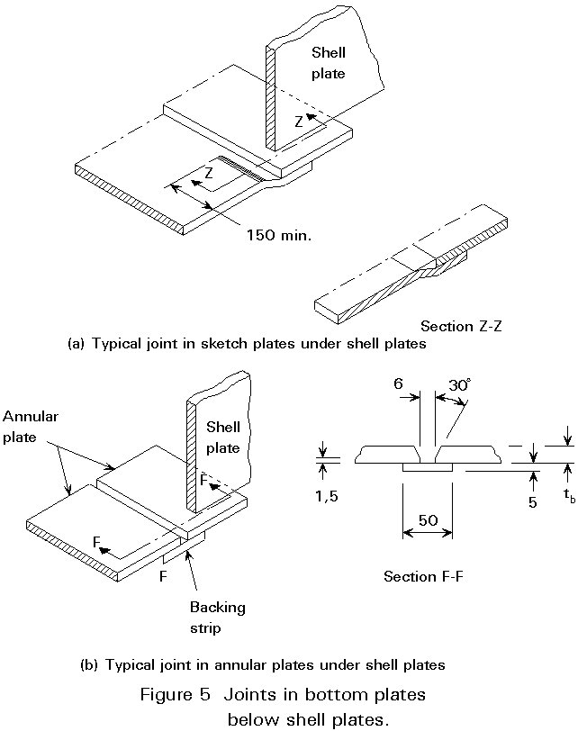
The shell sits on the sketch or annular plates, just inside the perimeter and is fillet welded to them (see Figure 5).
The bottom plates act principally as a seal to the tank. The only load they carry, apart from local stiffening to the bottom of the shell, is the pressure from the contents, which is then transmitted directly to the base. Stress calculations are not normally required for the base, though BS 2654 sets out minimum thicknesses of plate depending on the size of the tank.
Water tanks may also have a steel bottom. In some circumstances a reinforced concrete slab is specified instead. There are no standard details for the connection between a shell and a concrete slab, though a simple arrangement of an angle welded to the bottom edge of the shell and bolted to the slab will usually suffice.
Vertical cylinder tanks carry the hydrostatic pressures by simple hoop tension. No circumferential stiffening is needed for this action. The circumferential tension in the shell will vary directly, in a vertical direction, according to the head of fluid at any given level. For a uniform shell thickness, the calculation of stresses is therefore straightforward. At a water depth H, the stress is given by:
![]()
where D is the diameter of the tank
t is the thickness of the plate
r is the density of the fluid
g is the gravity constant
For practical reasons, it is necessary to build up the shell from a number of fairly small rectangular pieces of plate, butt welded together. Each piece will be cylindrically curved and it is convenient to build up the shell in a number of rings, or courses, one on top of the other. This technique provides, at least for deeper tanks, a convenient opportunity to use thicker plates in the lower rings and thinner plates in the upper rings.
The lowest course of plates is fully welded to the bottom plate of the tank providing radial restraint to the bottom edge of the plate. Similarly, the bottom edge of any course which sits on top of a thicker course is somewhat restrained because the thicker plate is stiffer. The effect of this on the hoop stresses is illustrated in Figure 6.
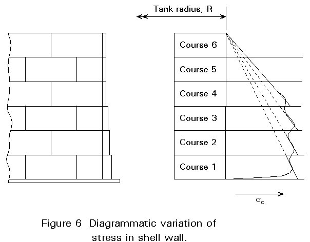
Consequently, because of these restraints, an empirical adjustment is introduced into the design rules which effectively requires that any course is simply designed for the pressure 300mm above the bottom edge of the course, rather than the greater pressure at the bottom edge. (This is known as the 'one foot rule' in API 650 [2].)
When the load due to internal pressure is taken into account and an allowance for corrosion loss is introduced, the resulting design equation is of the form in BS 2654:
![]()
where t is the calculated minimum thickness (mm)
w is the maximum density of the fluid (kg/l)
H is the height of fluid above the bottom of the course being designed (m)
S is the allowable design stress (N/mm2)
p is the design pressure (pressure tanks only) (mbar)
c is the corrosion allowance (mm)
The allowable design stress in tension in the shell is generally taken to be a suitable fraction of the material yield stress. BS 2654 defines it as two-thirds of the yield stress, thus giving an overall factor of 1,5 on the plastic strength of the plate. API650 also uses two-thirds of the yield stress, but additionally limits the design stress to a smaller fraction of the ultimate strength; for higher strength steels, this is slightly more restrictive. Further, API650 allows a slightly higher stress during the hydrostatic test than the allowable design stress for service conditions when the relative density is less than 1,0.
Each course is made of a number of plates, butt welded along the vertical join between the plates. Each course is butt welded to the course below along a circumferential line. Good weld procedures can minimise the distortions or deviations from the ideal flat or curved line of the surface across the weld, but some imperfection is inevitable, especially with thin material. Consequently the rules call for the vertical seams to be staggered from one course to the next - at least one third of the length of the individual plates, if possible.
Holes in the shell for inlet/outlet nozzles or access manholes cause a local increase in circumferential stresses. This increase is catered for by requiring the provision of reinforcing plates. These plates may take the form of a circular doubling plate welded around the hole or of an inset piece of thicker plate. The nozzle provides some stiffening to the edge of the hole; it may also be made of sufficient size that shell reinforcement can be omitted.
The cylindrical shell has to carry its weight, and the weight of the roof which it supports, as an axial stress. In addition, wind loading on the tank contributes tensile axial stress on one side of the tank and compressive stress on the other.
A thin-walled cylinder under a sufficient axial load will of course buckle locally, or wrinkle. The critical value of this stress, for a perfect cylinder, can be obtained from classical theory and, for steel, has the value:
![]()
In practice, imperfect shells buckle at a much lower stress; an allowable stress level of as little as a tenth of the above might be more appropriate. However, in normal service the axial stresses in shells suitable to carry the circumferential loads for the size of tank used for oil and water storage are much smaller than even this level of stress. The calculation of axial stress is therefore not even called for in codes, such as BS 2654 and API650, for the service conditions.
But under seismic conditions, larger stresses result because of the large overturning moment when the tank is full. In that case the axial stresses must be calculated. Axial stress due to overturning moment, M, is given simply by the expression:
sa = 4M/ptD2
In BS 2654 the axial stress under seismic conditions is limited to 0.20Et/R, which is considered a reasonable value when the cylinder is also under internal hydrostatic pressure. API650 uses a similar value, provided that the internal pressure exceeds a value which depends on the tank size.
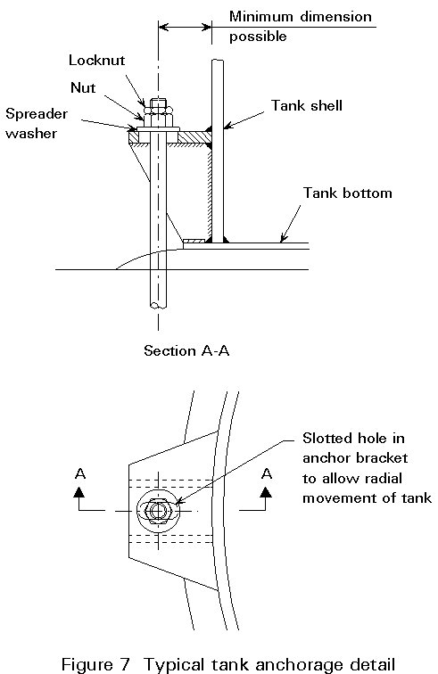
Although axial stresses do not need to be calculated for service conditions, the tank does have to be checked for uplift when it is empty and subject to wind loading. If necessary, anchorages must be provided; a typical example is shown in Figure 7.
A tank with a fixed roof is considered to be adequately restrained in its cylindrical shape by the roof; no additional stiffening is needed at the top of the shell, except possibly as part of an effective compression ring (see Section 5.2).
At the top of an open tank (or one with a floating roof), circumferential stiffening is needed to maintain the roundness of the tank when it is subject to wind load. This stiffening is particularly necessary when the tank is empty.
The calculation of the stability of stiffened tanks is a complex matter. Fortunately, investigations into the subject have led to an empirical formula, based on work by De Wit, which is easily applied in design. In BS 2654 this formula is expressed as a required minimum section modulus given by:
Z = 0,058 D2 H
where Z is the (elastic) section modulus (cm3) of the effective section of the ring girder, including a width of shell plate acting with the added stiffener
D is the tank diameter (m)
H is the height of the tank (m)
The formula presumes a design wind speed of 45 m/s. For other wind speeds it may be modified by multiplying by the ratio of the basic wind pressure at the design speed to that at 45 m/s, i.e. by (V/45)2.
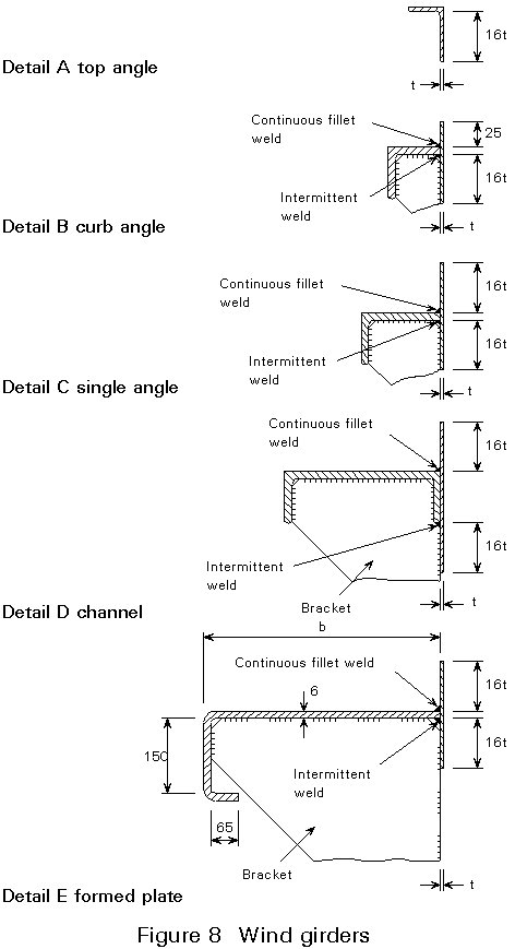
Wind girders are usually formed by welding an angle or a channel around the top edge of the shell. Examples are shown in Figure 8. Note that continuous fillet welds should always be used on the upper edge of the connection, to avoid a corrosion trap.
It is recognised that application of the above formula to tanks over 60 m diameter leads to unnecessarily large wind girders; the code allows the size to be limited to that needed for a 60 m tank.
Primary wind girders are normally external to the tank. Settlement tanks usually require a gutter around the inside edge of the tank, into which the water spills and passes to the outlet. Although this detail is not covered in the code, a suitable gutter detail can participate as a primary wind girder, provided it is relatively close to the top of the tank. In that event a kerb angle is also required at the free edge; the arrangement of a low ring girder and a kerb angle is covered by the design rules.
Although the primary wind girder or the roof will stabilise the tank over its full height, local buckling can occur in empty tall tanks between the top of the tank and its base. To prevent this local buckling, secondary wind girders are introduced at intervals in the height of the tank. The determination of the number and position of these secondary wind girders is dealt with in BS 2654 (but not in API 650).
The procedure is based on determining the length of tube for which, with the ends held circular, the elastic critical buckling will occur at a given uniform external pressure. Such buckling would also occur in a longer tube which is restrained at intervals equal to that length.
The critical stress for a length of tube, l, of radius R and thickness t, is given in Roark [4] by the formula:
Using values of E and u for steel, rearranging and simplifying, this reduces approximately to the expression in the code:
where D is the diameter of the shell (m)
Hp is the maximum permitted spacing of rings (m)
(equivalent to critical length, l)
tmin is the thickness of the shell plate (mm)
Vw is the design wind speed (m/s)
va is the vacuum (mbar)
However, tank shells in practice are made up of courses, and the thickness of the plating increases from the top to the bottom. Fortunately, this non-uniform situation can be converted into an equivalent uniform situation by noting that the critical length l (or maximum spacing Hp) is proportional to t5/2. Taking the thinnest plate (the top course) as reference (tmin), courses of height h and thickness t can be converted to an equivalent height of a tube of the thin plate which has the same effective slenderness by applying the correction:
![]()
where t is the thickness of each course in turn
He is the equivalent height of each course at a thickness of tmin
The equivalent heights of all the courses are added to give the total equivalent height (length of tube) and divided by the critical length Hp to determine the minimum number of intervals and thus the number of intermediate rings. The positions of the intermediate rings, which are equally spaced on the equivalent tube, must be established by converting positions on the tube back to positions on the tank, by the reverse of the above procedure.
The whole process is illustrated by an example in BS 2654.
The stiffening is achieved by welding an angle to the surface of the shell plate in the same manner as for the primary wind girder. Minimum sizes for this angle are given in the code [1].
Fixed roofs of cylindrical tanks are formed of steel plate and are of either conical or domed (spherically curved) configuration. The steel plates can be entirely self supporting (by 'membrane' action), or they may rest on top of some form of support structure.
Membrane roofs are more difficult to erect - they require some temporary support during placing and welding - and are usually found only on smaller tanks.
Permanent support steelwork for the roof plate may either span the complete diameter of the tank or may in turn be supported on columns inside the tank. The use of a single central column is particularly effective in relatively small tanks (15-20 m diameter), for example.
The main members of the support steelwork are, naturally, radial to the tank. They can be simple rolled beam sections or, for larger tanks, they can be fabricated trusses.
Roof plates are usually lapped and fillet welded to one another. For low pressure tanks, they do not need to be welded to any structure which supports them, but they must normally be welded to the top of the shell.
In a membrane roof, the forces from dead and imposed loads are resisted by compressive radial stresses. The net upward forces from internal pressure minus dead load are resisted by tensile radial stresses.
Conical roofs usually have a slope of 1:5. Spherical roofs usually have a radius of curvature between 0,8 and 1,5 times the diameter of the tank.
Limitations on buckling under radial compression are expressed in BS2654 as:
![]()
where R1 is the radius of curvature of the roof (m)
Pe is the external loading plus self weight (kN/m2)
E is Young's modulus (N/mm2)
tr is the roof plate thickness (mm)
For conical roofs, R1 is taken as the radius of the shell divided by the sine of the angle between the roof and the horizontal, i.e. R1 = R/sinq .
Using a value of Pe = 1,7 kN/m2, i.e. 1,2 kN/m2, superimposed load plus 0,5kN/m2 for dead load, (equivalent to about 6 mm plate thickness) and the E value for steel, gives:
tr = 0,36 R1
A similar expression is given in API650, expressed in imperial units and for a loading of 45lb/ft2 (= 2,2 kN/m2).
For tensile forces, stresses are limited to:
![]() (for spherical roofs)
(for spherical roofs)
![]() (for conical roofs)
(for conical roofs)
where h is the joint efficiency factor
S is the allowable design stress (in N/mm2)
p is the internal pressure (in mbar)
Although lapped and double fillet welded joints are acceptable, they have a joint efficiency factor of only 0,5; butt welded joints have a factor of 1,0.
For downward loads, the radial compression is complemented by ring tension.
For upward loads, i.e. under internal pressure, the radial tension has to be complemented by a circumferential compression. This compression can only be provided by the junction section between roof and shell. This is expressed as a requirement for a minimum area of the effective section, as shown in Figure 9:
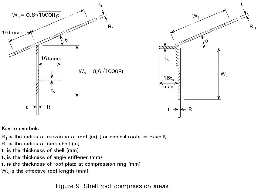
![]()
where Sc is the allowable compressive stress (in N/mm2)
R is the radius of the tank (in m)
q is the slope of the roof at roof-shell connection
The allowable compressive stress for this region is taken to be 120 N/mm2 in BS2654 [1].
Radial members supporting the roof plate permit the plate thickness to be kept to a minimum. They greatly facilitate the construction of the roof.
Radial beams are arranged such that the span of the plate between them is kept down to a minimum of about 2 m. This limit allows the use of 5 mm plate for the roof. The plate simply lies on the beams and is not connected to them.
Supported roofs are most commonly of conical shape, although spherical roofs can be used if the radial beams are curved.
The roof support structure can either be self supporting or be supported on internal columns. Typical arrangements are shown in section in Figures 10 and 11. Self supporting roofs are essential when there is an internal floating cover.
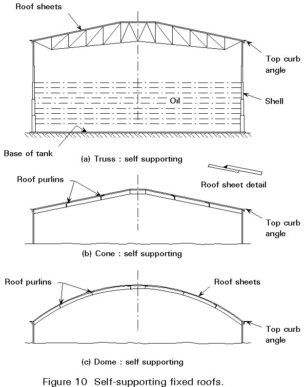
When columns are used to support the roof, the slope may be as low as 1:16. When the roof is self supporting it may be more economic to use a steeper roof.
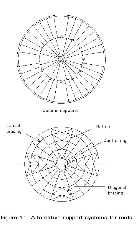
Not all radial members continue to the centre of the tank. Those that do may be considered as main support beams; the secondary radial members may be considered as rafters - they are supported at their inner ends on ring beams between the main support members. Where internal columns are used they will be beneath the main support members. Typical plan arrangements are shown in Figure 11.
The main support members need to be restrained at intervals to stabilise them against lateral-torsional buckling. Cross bracing is provided in selected bays.
In API650 it is permitted to assume that friction between the roof plate and the beam is adequate to restrain the compression flange of the secondary rafter beams, provided that they are not too deep; such restraint cannot be assumed for the main beams, however.
The main support members may be subject to bending and axial load. Where they are designed for axial thrust, the central ring must be designed as a compression ring; the top of the shell must be designed for the hoop forces associated with the axial forces in the support members.
Design of beams and support columns may generally follow conventional building code rules, though it must be noted that both BS 2654 and API650 are allowable stress codes. In the British code reference is therefore made to BS449 [5], rather than to a limit state code.
The shell/roof junction zone must be designed for compression, in the same way as described above for membrane roofs.
Venting has to be provided to cater for movement of the contents into and out of the tank and for temperature change of the air in the tank. Venting can be provided by pressure relief valves or by open vents.
For storage of petroleum products, emergency pressure relief has to be provided to cater for heating due to an external fire. Pressure relief can be achieved either by additional emergency venting or by designing the roof to shell joint as frangible (this means, principally, that the size of the fillet weld between the roof and the shell is limited in size - a limit of 5 mm is typical).
As mentioned in Section 5.4, tanks need to be vented to cater for the expansion and contraction of the air. In petroleum tanks, the free space above the contents contains an air/vapour mixture. When the mixture expands in the heat of the day, venting expels some of this vapour. At night, when the temperature drops, fresh air is drawn in and more of the contents evaporates to saturate the air. The continued breathing can result in substantial evaporation losses. Measures are needed to minimise these losses; floating roofs and covers are commonly used for this purpose.
A floating roof is sometimes provided instead of a fixed roof. The shell is then effectively open at the top and is designed accordingly.
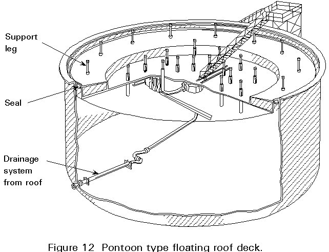
During service, a floating roof is completely supported on the liquid and must therefore be sufficiently buoyant; buoyancy is achieved by providing liquid-tight compartments in one of two forms of roof - pontoon type and double deck type.
A pontoon roof has an annular compartment, divided by bulkheads, and a central single skin diaphragm. The central diaphragm may need to be stiffened by radial beams.
A double deck roof is effectively a complete set of compartments over the whole diameter of the tank; two circular skins are joined to circumferential plates and bulkheads to form a disk or piston.
Both types of roof must remain buoyant even if some compartments are punctured (typically two compartments). The central deck of a pontoon roof should also be presumed to be punctured for this design condition.
Because the roof is open to the environment, it catches rain, which must be drained off. Drainage is achieved by a system on the roof which connects to flexible pipework inside the tank and thence through the shell or bottom plates to a discharge. The design is required to ensure that the roof continues to float in the event of a block in the drainage system which results in a surcharge of water on the roof (usually 250 mm of water).
When the tank is emptied, the roof cannot normally be allowed to fall to the bottom of the tank, because there is internal pipework; the roof is therefore fitted with legs which keep it clear of the bottom. At this stage the roof must be able to carry a superimposed load (1,2 kN/m2) plus any accumulated rainwater.
For maintenance of the drainage system and for access to nozzles through the roof for various purposes, maintenance personnel need access from the top of the shell to the roof whatever the level of contents in the tank. Access is usually achieved by a movable ladder or stairway, pinned to the shell and resting on the roof. For maintenance of the tank when it is empty, an access manhole must be provided through the roof.
A typical arrangement of a pontoon type roof is shown in Figure 12.
Where a cover to the contents is provided inside a fixed roof tank, to reduce evaporation or ingress of contaminants (e.g. water or sand), a much lighter cover or screen can be provided.
Such a cover is likely to be manufactured from lighter materials than steel, though a shallow steel pan can sometimes be provided. The cover does not need to be provided with access ladders, nor to be designed for surcharge. It does have to be designed to be supported at low level when the tank is empty and to carry a small live load in that condition.
Detailed recommendations for the design of internal floating covers are given in Appendix E of BS 2654 [1].
Access is required inside fixed roof tanks for maintenance and inspection purposes. Such access can be provided through the roof or through the shell wall. Manholes through the roof have the advantage that they are always accessible, even when the tank is full. Access through the shell wall is more convenient for cleaning out (some access holes are D-shaped and flush with the bottom for cleaning out purposes).
A manhole through a roof should be at least 500 mm diameter. Stiffening arrangements around the hole in the roof plate, and the type of cover, depend on the design of the roof. Access to the roof manhole must be provided by ladders, with suitable handrails and walkways on the roof.
A manhole through the shell wall should be at least 600 mm diameter and is normally positioned just above the bottom of the tank. A typical detail is shown in section in Figure 13. Further details of this example, and details of clean-out openings, are given in BS2654 [1].
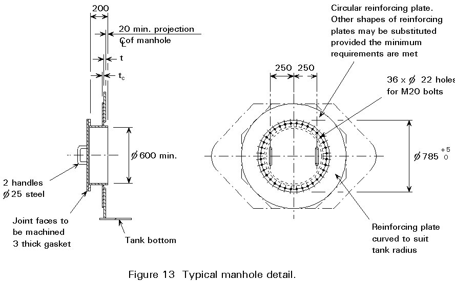
Clearly, the cutting of an opening in the shell interferes with the structural action of the shell. The loss of section of shell plate is compensated by providing additional cross-section area equal to 75% of that lost. The area must be provided within a circular region around the hole, though the actual reinforcement should extend beyond that region. Reinforcement can be provided in one of three ways:
(i) a reinforcing plate welded onto the shell plate (similar to the section in Figure 13)
(ii) an insert of thicker plate locally (in which the manhole is cut)
(iii) a thicker shell plate than that required for that course of the shell
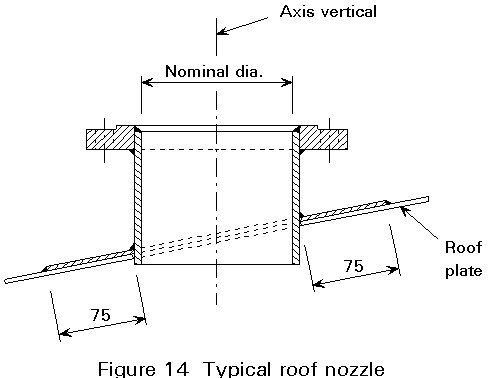
As well as manholes for access and cleaning out, nozzles are required through the shell roof and bottom for inlet, outlet, and drainage pipes, and for vents in the roof. They are normally made by welding a cylindrical section of plate into a circular hole in the structural plate. For small nozzles, no reinforcement is necessary, the extra material is considered sufficient. Larger holes must be reinforced in the same way as manholes. An example of a roof nozzle detail is shown in Figure 14.
[1] BS 2654: 1984, Specification for manufacture of vertical steel welded storage tanks with butt-welded shells for the petroleum industry, British Standards Institution, London.
[2] API 650, Welded Steel Tanks for Oil Storage, 8th Edition, November 1988, API.
[3] BS EN 10025, 1990, Hot Rolled Products of Non-alloy Structural Steels and their Technical Delivery Conditions, British Standards Institution, London.
[4] Young, W. C., Roark's Formulas for Stress and Strain, McGraw Hill, 1989.
[5] BS 449: Part 2: 1969, Specification for the Use of Structural Steel in Building, British Standards Institution, London.
Appendix A Differences between BS 2654 and API 650
The following are the principal differences between the British Standard, BS 2654 [1] and the American Petroleum Institute Standard, API650 [2]:
(a) API 650 specifies different allowable stresses for service and water testing. BS 2654 specifies an allowable stress for water testing only, which will allow oils with any specific gravity up to 1 to be stored in the tank.
(b) The allowable design stresses of BS 2654 are based on guaranteed minimum yield strength whereas the design stresses of API 650 are based on the guaranteed minimum ultimate tensile strength.
(c) BS 2654 specifies more stringent requirements for the weldability of the shell plates.
(d) The notch ductility requirements of BS 2654 are based on the results of a great number of wide plate tests. This system considers a steel acceptable if, for the required thickness, the test plate does not fail at test temperature before it has yielded at least 0,5%. This system gives the same safety factor for all thicknesses.
In API 650 a fixed value and test temperature is given for the impact tests for all thicknesses. As the tendency to brittle fracture increases with increasing plate thickness it means that API 650 in fact allows a lower safety factor for large tanks than for smaller ones.
(e) The steels specified by API 650 guarantee their notch ductility by chemical analysis but without guaranteed impact values. BS 2654 requires guaranteed impact values where necessary.
(f) BS 2654 gives a clearer picture of how to determine the size and location of secondary wind girders.