ESDEP WG 12
FATIGUE
To summarize the main factors affecting the fatigue strength, as opposed to the static strength, of welded joints and to illustrate the method of carrying out a fatigue check.
Lecture 12.10: Basics of Fracture Mechanics
Lecture 12.11: Stress Analysis of Cracked Bodies
Lecture 12.12: Determination of Stress Intensity Factors
Lecture 12.14: Fracture Mechanics: Structural Engineering Applications
Lecture 12.15: Fracture Mechanics Applied to Fitness for Purpose
After separating out initiation and propagation aspects of fatigue behaviour the lecture introduces the Paris law which describes the rate of fatigue crack propagation in terms of stress intensity factor range. Integration of the Paris law to give life for crack growth from initial to final sizes is described for constant amplitude loading and then extended to variable amplitude loading to show consistency with Miners law. The effects of threshold behaviour, residual stresses and effective stress intensity factor in crack closure behaviour are described.
When a component or structural member is subject to fluctuations in stress, it may lead to the development of fatigue cracks. Fatigue cracks extend slowly, generally with a very small increment of crack growth occurring with each cycle, and with little or no evidence of plastic deformation. The cracks can continue to grow until they cause complete failure of the component, member or structure by fast fracture, plastic collapse or other mode which prevents service duties being performed.
In laboratory tests on smooth polished specimens, each stress fluctuations causes a movement of dislocations until some slip planes lock and microscopic slip protrusions occur. Some authorities describe the formation of persistent slip bands as Stage 1, and the development of protrusions and minute fissures as Stage 2. The further development of these fissures into a macroscopic crack and its subsequent propagation is Stage 3.
The stages prior to the formation of a macroscopic crack represent the initiation life of the component whilst the remaining life after formation of such a crack is the propagation life. Thus the overall fatigue life of a component in general is as follows:
Total life = Initiation life + Propagation life
For cases where initial cracks are present the initiation life disappears and the whole life is occupied by the propagation of the crack from the initial size to a final size which is determined either by instantaneous fracture or by plastic collapse of the remaining cross-section. In some applications the presence of initial crack-like flaws is inherent to the manufacturing process. A particularly important case where this applies is in welded structures where tiny slag intrusions of the order of 0,1 to 0,4 mm depth occur in the partially melted region at the weld toe. The fatigue behaviour of welded joints is therefore dominated by the propagation life.
As indicated in Lecture 12.11 the topic of fracture mechanics is concerned with analysis of crack tip stress fields and their effects on failure mechanisms. The application of fracture mechanics to fatigue behaviour is concerned with the propagation life since it is only during this stage that a macroscopic crack is present. Thus for situations where no initial flaw is present, fracture mechanics analyses can be used to estimate the propagation part of the total life from assumed initial to final flaw size. It is then necessary also to estimate the initiation life and add this to the propagation life to get an estimate of the total life. For welded structures however the propagation life gives a good estimate of the total life provided realistic assumptions are made about initial and final crack sizes.
The proposal that the rate of crack propagation per cycle should be controlled by the range of the stress intensity factor for the cycle was first made by P C Paris as part of his research work. The general relationship now known universally as the Paris Law is as follows:
![]() = C(DK)m
(1)
= C(DK)m
(1)
where:
da/dN is the rate of crack growth per cycle
D
K is the range of stress intensity factor at the crack tipC and m are material constants (although not necessarily truly constant)
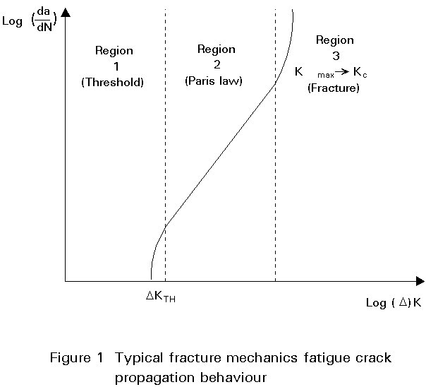
Experimental work to investigate the relationship between fatigue crack growth rate and range of stress intensity factor can be presented on a graph of da/dN against DK. In general, such a graph on log-log scales shows three regions. At the bottom end there is a threshold region of DK below which cracks do not propagate. This threshold value, DKm, is dependent on both mean stress and environmental conditions. At the top end of the graph the rate of fatigue crack propagation may be increased if the upper end of the applied stress intensity factor range approaches the material fracture toughness. In between these regions the graph is generally linear on logarithmic scales. By taking logarithms of both sides of Equation (1) it can be seen that it predicts that log da/dN should be proportional to log DK, so that the slope of the straight line is the constant m, and the position of the line is determined by the constant C. Thus the predictions of the Paris law are confirmed by experiment for the central region of behaviour as shown in Figure 1.
There have been various attempts to extend the validity of the Paris law to cover the whole range of behaviour. Some of these attempts will be discussed later. Many valuable results can be derived using the simple Paris law without the complications of the other proposals. These aspects will be examined first.
The value of the crack propagation law exponent m is found to lie between about 2,6 and 3,6 for different materials and conditions. A typical value often taken for structural steels is m = 3,0. The corresponding value of C for crack propagation of steels in air is about 2,0 ´ 10-13 in N/mm-3/2 units giving crack propagation rate in mm/cycle. (The equivalent value of C in MPa ![]() units is 6,32 ´ 10-15 for DK in the same units, giving da/dN in m/cycle).
units is 6,32 ´ 10-15 for DK in the same units, giving da/dN in m/cycle).
For the simple case of a central crack of length 2a in an infinite plate subject to remote fluctuating tension stress range Ds, the stress intensity factor range is given by:
D
K = DsPutting this value into the expression of the Paris law, the following result is obtained:
![]() = C (Ds
= C (Ds ![]() )m
(3)
)m
(3)
This can be re-arranged as a simple differential equation as follows:
![]() = Ds (S
= Ds (S ![]() )m dN
(4)
)m dN
(4)
This expression can be integrated directly, and for the case of m = 3 for example, this gives:
![]() = Ds (S
= Ds (S ![]() )3 N
(5)
)3 N
(5)
For given initial and final crack sizes and material properties this is equivalent to:
S3 N = Constant (6)
Use of this approach is shown in Example 1 below.
Example 1
Problem A thick plate has an extended length surface crack of height 2 mm perpendicular to the surface and to fluctuating applied stresses with a range of 100 N/mm2. Assuming that the Paris law is valid with C = 2 ´ 10-13 and m=3, determine the life for the crack to grow to a height of 10 mm.
Solution Integration of the Paris law as in Equation (5) gives:
 = 2 ´ 10-13 (1,12 ´ 100 ´
 ![]() )3 ´ N (7)
)3 ´ N (7)
therefore:
N = 0,782 / [2 ×10-13 × 198,53] = 500,000 cycles (8)
It should be noted that the above analysis is only strictly valid for the case of the surface crack in an infinite plate. In real finite geometries the expression for the stress intensity factor includes the Y coefficient which may itself be a function of the crack size dimension a. This effects the integration of the left hand side of Equation (4) which then becomes:
![]() = C (Ds
= C (Ds ![]() )m dN
(9)
)m dN
(9)
S-N design curves for welded details are effectively of the form of Equation (6), the constant being different for different geometries (equivalent to different Y values).
For weld toe geometries the magnification of the stress intensity factor which occurs over crack depths up to 20% of the thickness can be represented by the term Mk, where:
D
K = Mk Ds Yuand Yu is the appropriate Y value for a crack of the same shape in a plate without stress concentration effects.
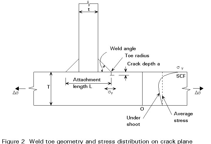
Research at the Welding Institute and at UMIST in the United Kingdom has produced parametric equations for Mk in terms of weld attachment length-to-thickness ratio, weld angle and weld toe radius for geometries of the form shown in Figure 2. An approximate expression for Mk is as follows:
Mk = p ![]() (11)
(11)
where p and q are constants dependent on the detailed weld geometry. More complex expressions for Mk have been derived in the UMIST work which allow for all three of the weld toe geometric parameters. This work has also shown the need for a further coefficient/correction factor to allow for the crack shape aspect ratio and for the 'undershoot' effect of the stress distribution across the thickness which is necessary to compensate for the stress concentration at the surface as shown in Figure 2.
Provided the overall effect of geometry can be expressed in the form of parametric equations, the crack propagation integral of Equation (9) can be evaluated numerically in incremental steps. Furthermore since the stress intensity factor varies around the perimeter of the crack front of a semi-elliptical surface crack, and the crack growth rate depends on (DK)m, it can be seen that the crack will grow at different rates at different positions on its perimeter. Thus the crack will change its shape as it grows. Therefore the stress intensity factor has to be re-evaluated incrementally due to both crack growth and change of shape. A number of researchers have developed computer programs to evaluate the crack propagation integral progressively for different geometric applications and have found good agreement with experimental data. The power of the approach is its ability to evaluate a wide range of geometric effects and to predict the significance of imperfections and defects on fatigue performance.
Sequential block loading
Consider the propagation of a fatigue crack under a sequence of blocks of different levels of constant amplitude loading as shown in Figure 3.
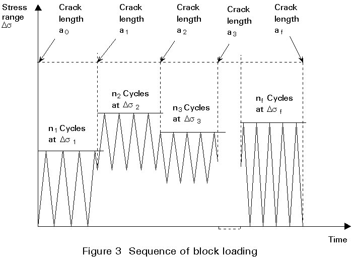
The crack grows from size a0 to a1 under n1 cycles of stress range Ds1, from a1 to a2 under n2 cycles of stress range Ds2, from a2 to a3 under n3 cycles of stress range Ds3, etc., up to the final block of cycles mf at stress range Dsf taking the crack up to its final size af. Crack growth for each stage will be described by the following equation:
 (12)
(12)
 (13)
(13)
 (14)
(14)
 (15)
(15)
etc.
Examination of these equations shows that in the terms on the left hand side the top limit for one integral is the same as the bottom limit for the next integral as they represent the crack size at the change from one block of loading to the next. If all the equations are added together then the intermediate limits on the left hand side all cancel out, and the following equation results:
 (16)
(16)
If each of the different stress range blocks had been applied as constant amplitude loading to grow the crack completely from its initial size a0 to its final size af, with lives Ni corresponding to stress ranges Dsi the crack growth equations would be:
![]() = C(
= C(![]() )3(Ds13N1 = C(
)3(Ds13N1 = C(![]() )3Ds23N2 = C(
)3Ds23N2 = C(![]() )3Ds33N3 =... = C(
)3Ds33N3 =... = C(![]() )3 Dsf3 Nf
(16)
)3 Dsf3 Nf
(16)
If Equation (14) is divided by Equation (15), using the appropriate term on the right hand side of Equation (15) containing the same Dsi as the successive terms in Equation (14), the result is the well known linear damage relationship, Miner's Law:
![]() = 1
= 1
It should be noted that this fracture mechanics version of Miner's Law has been derived on the assumption that there is no interaction between successive blocks of loading at different stress ranges and without taking any account of effects of mean stress or stress ratio on the crack propagation constants for each block of loading. However, in principle, the length of each block could be reduced to a single cycle, so that the analysis predicts that Miner's Law should hold for random variable amplitude loading. The fact that in practice significant retardation effects are observed for occasional overloads and acceleration effects for underloads, and that Miner's Law damage summation figures differing significantly from 1 are often obtained for different loading spectra, suggests that some of the underlying assumptions of the fracture mechanics analysis are not valid. In fact these effects can be taken into account in more sophisticated fracture mechanics analyses by considering crack closure and plasticity effects.
Example 2
Problem The plate of example 1 with initial extended length crack of height
2 mm is subject to the following combination of stress ranges and cycles under variable amplitude loading for a period of five years. Assuming that the Paris Law is valid, with constants C = 2 ´ 10-13 and m = 3, determine the final crack height when all cycles have been applied.
|
Stress range N/mm2 |
Number of cycles per year |
|
120 100 80 60 40 20 |
102 103 104 105 106 107 |
Solution Integration of Equation (16) gives the following results:
 = 1,114 ´ 10-12 (1203 ´ 102 + 1003 ´ 103 + 803 ´ 104 - 603 ´ 105 + 403 ´ 106 + 203 ´ 107) ´ 5
(19)
= 1,114 ´ 10-12 (1203 ´ 102 + 1003 ´ 103 + 803 ´ 104 - 603 ´ 105 + 403 ´ 106 + 203 ´ 107) ´ 5
(19)
therefore:
![]() = 2 ´ 10-13 ´ 5,568 ´ 1,7189 ´ 10" = 0,957 (20)
= 2 ´ 10-13 ´ 5,568 ´ 1,7189 ´ 10" = 0,957 (20)
therefore af = 19,16 mm.
For constant amplitude loading, threshold effects are straightforward; if the applied stress intensity factor range is less than the threshold value, the rate of fatigue crack propagation is zero. When the inherent size of initial flaw or imperfection associated with a particular material and fabricated geometry is considered, it can be seen that the threshold stress intensity factor will correspond to a fatigue limit stress level below which cracks will not develop. Thus fracture mechanics and conventional S-N approaches are again matched.
For variable amplitude loading, the effects of the threshold are more complex. At short crack lengths the lower stress ranges may be insufficient to make the stress intensity factor exceed the threshold but the higher stress ranges may be sufficient to cause crack propagation to occur. As the crack grows longer under the action of the higher stress ranges, so the stress intensity factor due to the lower stress ranges increases. These lower stress ranges will 'clip in' progressively to start driving the crack. It is then necessary to calculate the crack length at which each of the stress ranges 'clips in' and to carry out the integration of crack growth between limits for each of the these stages with the appropriate set of stress ranges active as shown in Example 3.
Example 3
Problem For the plate and loading of Example 2 the threshold stress intensity factor is 100 N/mm-3/2 and the loading is applied for eight years. Determine the crack sizes at which different stress levels 'clip in', and the resulting final crack size allowing for threshold effects.
Solution To determine the crack sizes at which the different stress levels 'clip in', it is necessary to use the equation:
D
Kth =This equation gives the following results for the stress ranges concerned, with a threshold value of 100 N/mm-3/2.
|
Stress range N/mm2 |
Threshold crack size mm |
|
120 100 80 60 40 20 |
0,18 0,25 0,40 0,70 1,58 6,34 |
From the above table it can be seen that for an initial crack size of 2 mm, all the stress ranges of 40 N/mm2 and above exceed the threshold from the start, but the stress range of 20 N/mm2 does not become effective until the crack has grown to a size of 6,34 mm. The crack propagation integration now has to be divided into two stages, from 2 mm to 6,34 mm, and from 6,34 mm to the final size as follows:
 = 1,114´10-12 (1203´102 + 1003´103 + 803´104 + 603´105
+ 403´106)xy (22)
where y is the number of years for the crack to grow to 6,34 mm under the stress ranges from 40 N/mm2 upwards. Solution of this equation leads to y = 6,05 years. For the total life of 8 years, the remaining life for the second stage with all stress ranges driving is 1,95 years. The integrated crack growth behaviour then becomes:
 = 1,114 ´ 10-12 (1203´102 + 1003´103 + 803´104 + 603´105
+ 403´106 + 203´107) 1,95 (23)
This leads to a final crack size of 22,5 mm. The effect of the threshold has been
to remove the damage caused by the lowest stress range until the crack has grown to 6,34 mm, and hence to extend the life for the crack to grow to the order of 20 mm from 5 to 8 years.
Residual stresses are an inevitable consequence of a number of fabrication processes and procedures, and are particularly important in welded steel structures. They have significant effects on fracture and fatigue. The effect on fatigue is to change the mean stress and stress ratio locally at the weld compared to the applied loading conditions. Thus at a welded joint where residual stresses are often at yield level in tension, constant amplitude fatigue loading leads to actual stresses at the weld which cycle from the yield strength downwards by the magnitude of the applied stress range. If the applied loading included stresses in the compressive region or which would cause crack closure so that part of the stress range is non-damaging, the effect of the residual stresses is to hold the crack open so that the whole of the stress range becomes damaging. As the crack grows away from the weld however it may run out of the tensile residual stress zone and into a compressive region. In these circumstances part of the applied stress range will become non-effective. To deal with these types of situation it is useful to use the fracture mechanics crack propagation equations with an 'effective' stress intensity factor range allowing for crack closure effects, and to divide the crack growth into stages defined by crack sizes at which the effective stress intensity factor range changes due to the crack tip moving into different residual stress regions.