ESDEP WG 12
FATIGUE
To describe the basic principles of the different methods of determining stress intensity factors for different geometries of component.
Lecture 12.10 : Basics of Fracture Mechanics
Lecture 12.11 : Stress Analysis of Cracked Bodies
Lecture 12.14 : Fracture Mechanics Structural Engineering Applications
Lecture 12.15 : Fracture Mechanics Applied to Fitness for Purpose
The lecture starts with a reminder of the basic definition of the stress intensity factor as the parameter controlling crack tip stress, displacement and energy conditions for linear elastic materials. Some classical cases for which analytical solutions for the stress intensity factor are available are described together with the basis for combining solutions by superposition. The two main numerical analysis methods for determining stress intensity factors are then described, namely weight function methods and finite element methods including some details of the way in which the stress intensity factor is derived from the basic analysis results. Treatments for stress concentration regions are also described with particular reference to welded joints.
In Lecture 12.10: Basics of Fracture Mechanics, the concept of the stress intensity factor (K) was introduced as the parameter which defines the stress and strain fields at the tip of a crack, i.e. on the plane of the crack ahead of the crack tip the stress normal to the crack is given by:
sy = K / Ö(2pr) (1)
where r is a small distance ahead of the crack tip on the crack plane.
The stress intensity factor K also controls the opening displacements of the crack faces within the crack close to the tip for elastic conditions as follows:
sd = (4/pE) KÖ(2pr) (2)
where r is a small distance back from the crack tip within the crack.
In addition, the stress intensity factor K is linked to the Griffith strain energy release rate G (crack extension force) by the relationship:
K2 = E'G (3)
where E' = E for plane stress
and E' = E/(1-u2) for plane strain
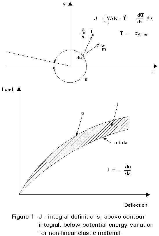
For non-linear materials a further important crack tip parameter is the J contour integral, J. As originally defined by Eshelby and by Rice, J was shown to be a path independent integral of strain energy density terms taken around the crack tip, with the path starting on the lower face of the crack and finishing on the upper face as shown in Figure 1.
The definition of J in these terms is as follows:
![]() (4a)
(4a)
where
W(e) = ò0 Jeij deij
![]()
where W is the strain energy density,
Ti are components of surface tractions moving through displacements dui,. The integration is carried out around any contour path anti-clockwise from one surface to the other enclosing the crack tip.
In addition to demonstrating path independence for this integral for two dimensional geometries with externally applied loading, Rice also showed that J was related to the change in potential energy with incremental increase in crack length, i.e. J can be thought of as a non-linear version of G and reduced to G for linear elastic materials. For a linear elastic material:
![]()
![]() (4b)
(4b)
The importance of all of the above observations is that, if methods are available to determine stress fields ahead of the crack tip, displacement fields within the crack, or strain energy fields related to G or J, then the stress intensity factor K can be determined from these results.
A number of classical cases where the stress intensity factor can be determined analytically were described in Lecture 12.10 on Basics of Fracture Mechanics. These cases included solutions for a central through-thickness crack, an embedded elliptical crack and a semi-elliptical surface crack all located in infinite plates and subject to remote tension loading. Reference was also made to the general form of expressions for the stress intensity factor for cases subject to remote stresses as either:
![]() (5)
(5)
where
MD is the finite width and thickness correction factors (Dimensions correction factor)
MS is the free surface correction factor
MP is the local plasticity at crack tip correction factor
MG is the stress gradient correction factor for local effect
E(F) is the crack shape correction factor
An example of using this expression for a stress concentration region at the end of a welded cover plate is given in the Appendix to this lecture.
or ![]() (6)
(6)
where
Mm and Mb are as defined in Section 5.
Two other cases where the results of classical analytical solutions are relevant to practical applications are the cases of a multiple array of co-linear cracks subject to remote loading and of a single crack subject to a pair of splitting forces applied to the crack faces. The multiple array case is shown in Figure 2, where the cracks are each of length 2a, and the spacing between their mid-length positions is W. The solution for the stress field for this case, where the cracks are subject to remote tension stress s in an infinite plate, can be obtained from the complex stress function approach of Westergaard used by Irwin to give the stress intensity factor as follows:
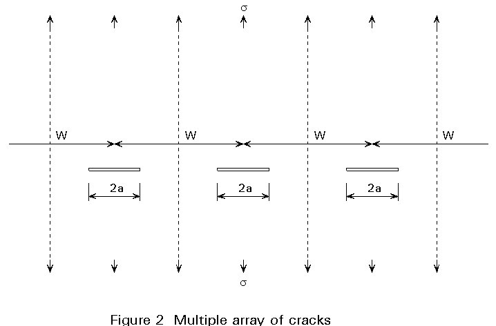
![]() (7)
(7)
This case of multiple cracks can be used to investigate the effects of interactions between adjacent cracks and of finite width of plates. It can be seen that when the ratio of a/W is small, this expression reduces to the same result as that for a single crack in an infinite plate, i.e. there is no interaction between the cracks. As a/W increases so the stress intensity factors increase above the corresponding value for single cracks of the same size. It will be left to the student to check that when the spacing between the tips of the adjacent cracks is equal to the crack length, i.e. W-2a = 2a, the stress intensity factor is increased by about 13% compared to the case of the single crack of the same length. This result is the basis for the recommendation in a number of defect acceptance codes that cracks may be treated as separate provided the ligament between them is at least equal to the adjacent crack size. The spacing W may also be considered as equivalent to the width of a series of finite plates each containing a single crack. Hence as the ratio a/W increases, the increase in K represents the effect of net section stresses and of the approaching edge of the plate. This interpretation is not strictly valid, however, as the stress distribution on the line of symmetry between the cracks does not reproduce fully the free edge condition. It does give reasonably good answers for ratios of a/W up to about 0,6.
The case of a single crack subject to a pair of splitting forces on the crack line is shown in Figure 3.
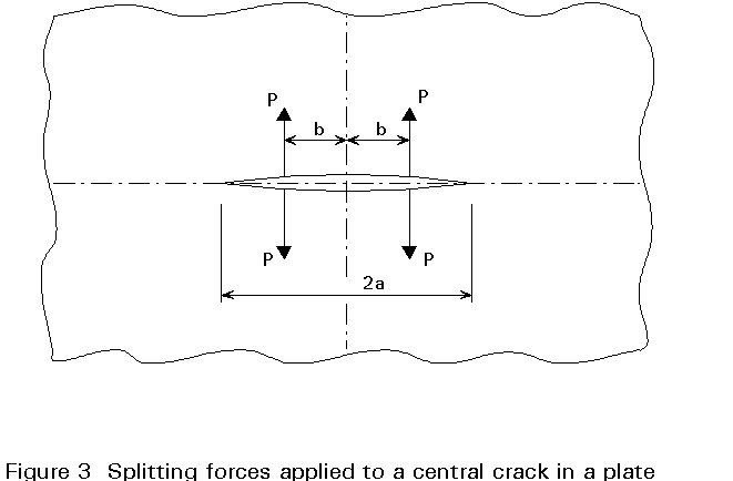
Again the solution can be obtained by use of the Westergaard complex stress functions and the resulting stress intensity factor is as follows:
 (8)
(8)
This result can be used to represent the effects of internal pressure inside a crack by integrating the splitting forces p applied at positions of b from 0 to a. As indicated in Lecture 12.10 the stress intensity factor for the internal pressure case is K = ![]() , i.e. the same as for the case of remotely applied tension.
, i.e. the same as for the case of remotely applied tension.
This is one example of a more general result which forms the basis of the weight function approach for determination of stress intensity factors.
If a cracked body subject to external loading or prescribed displacements at the boundary has forces applied to the crack surfaces to close the crack together, these forces must be equivalent to the stress distribution in an uncracked body of the same geometry subject to the same external loading. In the condition when the crack is closed together there is effectively no crack present and the stress intensity factor is zero. This can be regarded as equivalent to superposing the case of the cracked body with external loading minus the case of the same geometry of cracked body subject to the reverse of the crack surface loading necessary to close the crack together again. Since the total resultant stress intensity factor is zero, the stress intensity factor for the crack body subject to external loading must be the same as that for the same body subject to crack surface loading of the same distribution as would be present in the uncracked body over the region of the crack position. For many cases the cracked body with remote loading can be replaced by the same geometry with crack surface loading only to determine the stress intensity factor. This principle was first expounded by H F Bueckner and is known as Bueckner's principle.
When a pair of point forces P are applied to the opposite surfaces of a crack, they produce a stress intensity factor K at the crack tip as described for the case of two balanced pairs of splitting forces on a crack in an infinite plate in Equation (8). A further example is the case of an edge crack in a semi-infinite plate subject to concentrated forces P as shown in Figure 4.

The stress intensity factor for this case is given by:
 (9)
(9)
where F(x/a) is a tabulated function given by Hartranft and Sih [1].
A weight function is a function which gives the ratio of (the stress intensity factor at a crack tip due to the application of a stress s to an element of area dA on the crack surface) to (the stress itself).
Equation (9) may be used as a fundamental Green's function for generating solutions for stress intensity factors in crack problems involving an arbitrary distribution of tractions on the crack surfaces as shown in Figure 4b. Integrating Equation (9) from x=0 to x=a, the stress intensity factor for the edge crack subject to an arbitrary stress distribution p on the crack surfaces gives:
 (10)
(10)
This can be turned into a general summation for a two dimensional weight function expression in the form developed by Albrecht [2] as follows:
A more general weight function expression is given by the 'O' integral weight function developed by Core and Burns [3], as follows:
 (12)
(12)
where
s
is the stress applied to an element of crack surface area dA I is the distance from this point to the position where the K value is required{} represents the sum around the crack perimeter s of elemental lengths divided by distance to the point of stress application squared as shown in Figure 5.
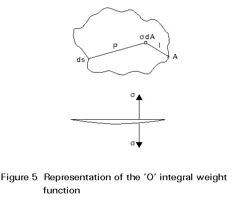
Evaluation of the 'O' integral is carried out by summing up the effects of different stress levels according to the uncracked stress distribution applied over the whole crack surface divided up into a network of elements.
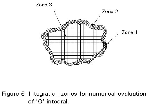
It will be seen that the expression given by Equation (12) involves two singularities, namely when 1=0 and when p=0. The evaluation of the numerical integration is carried out by dividing the crack area into three zones as shown in Figure 6. Zone A is a single element immediately at the position on the crack front where K is to be determined. Zone B is a series of elements around the remainder of the crack front perimeter. Zone C covers the remainder of the interior of the crack surface area. Careful attention is required to element sizes and aspect ratios to achieve accurate results. The 'O' integral formulation applies strictly to an embedded crack of arbitrary shape in an infinite body, but it is possible to apply correction factors for the effects of free surface and finite geometry effects.
Thus, one general method for determining stress intensity factors is to determine firstly the stress distribution in an uncracked body over the region where a crack is to be considered, e.g. by finite element analysis, and to use weight function approaches to determine the K value for any required crack geometry. Although the approach requires repeated use of the numerical integration of the weight function for a series of cracks as would be required to be considered during fatigue crack growth, it only requires one finite element analysis for the uncracked body and is generally an efficient overall process.
When finite element analysis is carried out, the first steps are to decide on the type of element to be used and on the mesh to be used to discretise the volume of the body concerned. Different types of element use different interpolating functions for displacements throughout each element. Each type has an inherent ability to deal with stress gradients within the element. For example, the simplest types of element are the constant stress or constant strain triangular elements. If an attempt is made to use these elements to analyse a body with steep stress gradients, a very fine mesh consisting of many elements must be used. This will be very inefficient on computing time. This problem can be reduced by using higher order elements which have the ability to represent linear or parabolic stress distributions within them. For example, 8 noded or 12 noded solid elements are often used when accurate stress analysis results are required from two dimensional complex geometries.
For example, 8 noded or 20 noded solid elements are often used when accurate stress analysis results are required from three dimensional complex geometries.
As indicated previously, the stress distribution at a crack tip subject to tension loading in elastic material, shows a singularity with infinite stresses. The stress intensity factor describes the way in which the stress declines from the singularity and clearly involves very steep stress gradients. For normal finite element analysis, it would appear at first sight that it would be very difficult to obtain anything like a realistic representation of elastic crack tip stress fields unless an inordinately fine mesh is used involving a very large number of elements and associated costs.
This problem can be overcome by use of special crack tip elements [4]. For two dimensional analyses (plane stress or plane strain) there are elements of degenerated triangular 20 moded type or 52 moded type based on a 12 isoparametric quadrilateral finite element. These elements are arranged into a fan focused at the crack tip by degenerating them into triangular elements by bringing two corners together at the same co-ordinates. In addition, the analysis moves the mid-points of the sides of the elements adjacent to the crack tip to the quarter points, as shown in Figure 7. The effect is to create an inverse square root singularity of stress ahead of the crack tip without having to go to a very fine mesh. It then remains to determine the value of the stress intensity factor from the results of this arrangement.
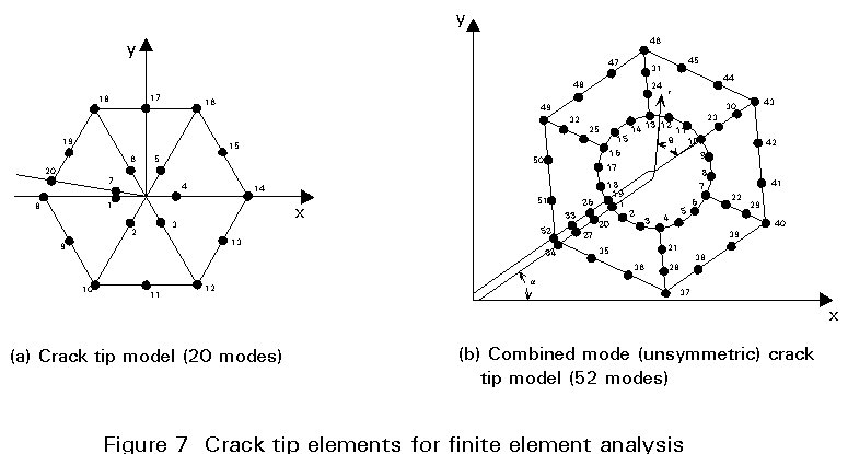
It has been pointed out that the stress intensity factor controls the stress ahead of the crack tip, the displacement with the crack just behind the tip and the strain energy fields around the crack tip. Because the stress gradients are so steep away from the singularity, the determination of K from stresses ahead of the crack is not very accurate. The displacement field within the crack has much more gradual variations and can be used to determine K quite accurately. The usual method is to determine the displacements at the first and second nodes back from the crack tip and use the formula of Equation (2) to derive K. A number of standard computer programs have been written which include special crack tip elements and the facility to carry out a J contour integral determination using any chosen contour around the crack tip. The normal procedure is to determine J on three paths around the crack, to check path independence, and to determine K from J using Equation (3). A variation on this procedure is the Virtual Crack Extension method developed by Parks. In this case the energy change associated with a small (virtual) increase in length of the crack is determined and this is equivalent to J (or G for linear elastic materials). The advantage of the strain energy or contour integral approaches is that they are evaluated at some distance from the crack tip itself and hence in regions where the stress and strain gradients are less severe.
The disadvantage of using finite element analysis of the crack body is that a new analysis of the whole body is required for each crack geometry to be considered. Hence, when one is considering fatigue crack growth, a series of results for progressively increasing crack sizes is required. Nevertheless, with modern computing power and facilities, there are many results for stress intensity factors obtained by finite element analysis of the complete cracked body.
A number of handbooks have been published which give solutions for stress intensity factors for a range of practical problems in the form of parametric equations or analytical expressions. Some of these stress intensity factors are given in Table 1 and others are listed in [1-10].
An extremely useful set of parametric equations has been developed by Raju and Newman [9] for the case of semi-elliptical surface cracks in flat plates of finite thickness and width, subject to either tension or bending stresses. These results were derived primarily by an extensive set of finite element analyses of different crack geometries followed by curve fitting to obtain the parametric equations. These equations enable the stress intensity factor to be obtained at any position around the crack front. This is particularly important when it is necessary to know the K value at the deepest point and at the ends of the crack at the surface to determine crack growth rates in fatigue analysis and allow for crack shape changes. The results are also very useful when the overall stress distribution can be divided into membrane and bending components since the K values due to the separate components can be determined and then added together to give the total K. The following general expression for the stress intensity factor is obtained:
![]() (13)
(13)
where Mm, Mb are coefficients determined from the Raju and Newman equations dependent on a/T and a/2c, sm, sb are membrane and bending components of stress, a is the crack height or depth, and Q is a crack shape parameter, given to sufficient accuracy by the expressions:
![]()
![]() (14)
(14)
![]()
![]() (15)
(15)
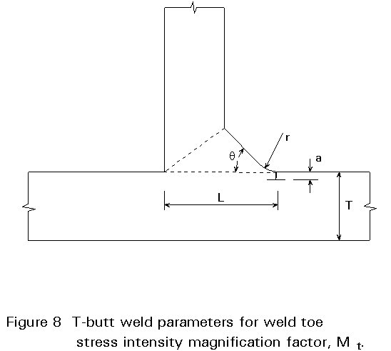
When the crack is located in a region of stress concentration there will be an increase in the stress intensity factor compared to regions away from the stress concentration. The overall effect depends on the relative size of the crack and the zone of stress concentration. Where the crack is small compared to the stress concentration zone, it will behave almost as if it is located in a region of uniform stress of magnitude equal to the stress concentration value. Where the crack is larger than the zone of stress concentration, it passes through a region of stress gradient and the final stress intensity factor is less than the result for treating the stress as uniform and equal to the SCF value. One important example of this which is particularly important in fatigue of welded structures is the stress intensity factor for cracks at the toes of fillet and T-butt welds as shown in Figure 8. For this case, a stress intensity magnification factor Mt is introduced to represent the multiplication necessary compared to the result for a crack of the same geometry subject to the same remote stresses in a flat plate without the weld being present.
A significant amount of work has been carried out at the Welding Institute (TWI) and at UMIST to derive parametric equations for Mt. The TWI results which are included also in PD 6493:1991 [10], have the following form:
![]() (16)
(16)
where p and q are constants for a particular geometry but depend on the ratio of weld attachment length on the surface to the main plate thickness T.
The UMIST results allow also for the effect of weld angle and weld toe radius and take the general form:
![]() (17)
(17)
where the coefficients Ci are given in parametric equations for tension or bending, involving the attachment length to thickness ratio, the weld angle and the toe radius.
Another important case for analysis of welded joints is the case of the stress intensity factor for the root of the unpenetrated land of a fillet weld subject to tension loading. The only work which seems to have been done on this is by Frank and Fisher whose results are included in PD 6493 1991, and by Saket at UMIST. Saket's results are as follows:
K = (2,8817 a/W - 0,074)Ktm for 0,25<a/W<0,45 (18)
where W = tp + 2tw, with tp being the attachment plate thickness, and tw the fillet throat thickness on one side of the plate, (two welds being assumed), and Ktm is given by:
![]() (19)
(19)
where sp is the remote tension stress in the attachment plate.
A summary of some cases of stress concentration and gradient factors for cracks at welded details is given in Table 2.
As indicated in Lecture 12.10, the effect of plasticity is to cause a real crack to have a stress intensity factor equivalent to a slightly longer notional crack in elastic material. The effect depends on the size of the plastic zone at the tip of the real crack. Under plane stress conditions the plastic zone is larger than under plane strain conditions where constraint effects inhibit yielding until higher stresses are reached.
Under compression loading, if the crack faces are forced into contact, the singularity effect is lost and the stress intensity factor is zero, since forces can be transmitted in bearing and there is no need for them to be diverted around the end of the crack. One of the significant effects of plasticity in fatigue is on the occurrence of crack closure behaviour when the crack faces come into contact and compression stress is then transmitted in bearing. Plasticity allows the crack tip to be stretched open so that on unloading the original crack surfaces would remain apart. As the crack propagates through the plastic zone under fatigue loading, however, the stretched material of the plastic zone forms a wake down the faces of the crack. These regions fill the gap on unloading despite the stretching at the tip. The net result is that the crack closes on itself at some stage during the unloading part of a fatigue cycle and does not re-open until the same load is reached on re-loading. Since there is no stress intensity factor when the crack is closed, fatigue damage only occurs when the crack faces separate again. This leads to the concept of an effective stress intensity factor given by:
DKeff = U.DK (20)
where U is a factor dependant on the stress ratio R and the yield strength through crack closure effects.
[1] Sih G.C. Handbook of stress intensity factors, Lehigh University, Bethlehem, Pennsylvania, USA, 1973.
[2] Albrecht P. and Yamada K. Rapid calculation of stress intensity factors, Journal of the Struct. Div., ASCE, Proc. 12742, Vol 103, No. St.2, 1977.
[3] Core M. and Burns D.J. Estimation of stress intensity factors for irregular cracks subject to arbitrary normal stress fields, Proc. 4th International Conference on Pressure Vessel Technology, I.Mech.E., London, Vol. 1, pp 139-147, 1980.
[4] Gifford L.N., Hilton P.D. Stress Intensity Factors by Enriched Finite Elements Engineering Fracture Mechanics, Vol. 10, pp 485-496, 1978.
[5] Tada H, Paris P and Irwin G.R. The stress analysis of cracks handbook, Del Research Corporation, Hellertown, Pa., USA, 1973.
[6] Rooke D.P. and Cartwright D.J. Compendium of stress intensity factors, HMSO, London, 1976.
[7] Rooke D.P., Baratte F.I. and Cartwright D.J. Simple methods of determining stress intensity factors, Engineering Fracture Mechanics, Vol. 14, 1981.
[8] Labbens R., Pellisier-Tanon A. and Heliot J. Practical methods for calculating stress intensity factors through weight functions. Mechanics of crack growth, ASTM STP 590, 1976.
[9] Raju I.S. and Newman J.C. Stress intensity factors for a wide range of semi-elliptical surface cracks in finite thickness plates. Eng. Fract. Mech. Vol. 11, pp 817-829, 1979.
[10] PD 6493, Guidance on methods for assessing the acceptability of flaws in fusion welded structures. BSI London, 2nd edition, 1991.
APPENDIX
NUMERICAL EXAMPLE
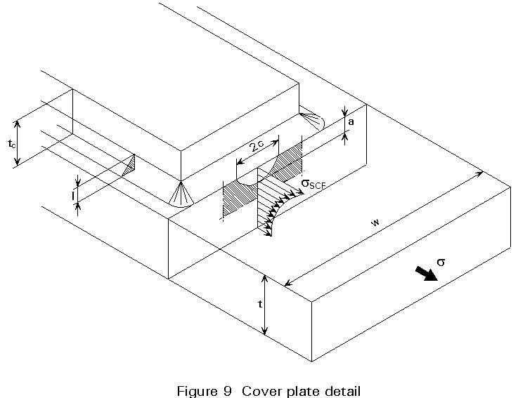
Estimate the stress intensity factor related to a semi-elliptical crack shape at the toe of a cover plate end weld (Figure 9)
|
Numerical Data |
crack depth, a = 3mm crack width, c = 8mm weld flank angle q = 45° weld leg = 15mm flange thickness = 40mm flange width = 600mm cover plate thickness = 25mm nominal tension stress smax = 300 N/mm2 |
Calculation
(a) Stress Gradient
kt = ![]()
(See Table 2)
(b) Stress Gradient Correction Factor
FG = ![]() (See Table 2)
(See Table 2)
(c) Free Surface Correction Factor
Fs = ![]()
(d) Finite Dimension Correction Factor
FD = 1
(e) Free Surface Correction Factor
Fs = ![]()
(f) Local Plasticity at Crack Tip
Fp = ^ (no correction for local plasticity considered)
Ki = ![]()
= ![]()
= ![]()
![]()
Table 1 - Some Solutions of Stress Intensity Factors
|
TWO DIMENSIONAL EDGE CRACK PROBLEMS |
|
TWO DIMENSIONAL CENTRE CRACK PROBLEMS |
|
|
|
Uniformly distributed stress K = 1,122 Ko
|
|
K = Ko |
|
|
Linearly varying stress K = 0,439 Ko
|
|
|
|
|
Concentrated splitting force
|
|
|
Table 2 - Stress concentration and stress gradient correction factors
|
CASE |
STRESS CONCENTRATION FACTOR kt |
FG STRESS GRADIENT FACTOR |
REFERENCES |
|
|
1 |
Transverse butt weld
|
|
Conditions : s =180° -q 135° £ f <180°circular arc overfill
where q = log (11,584 - 0,0588 f )/2,301 |
Gurney T.R. Fatigue of welded structures 2nd ed., Cambridge Univ. Press 1979 |
|
2 |
Transverse stiffener weld (non-load-carrying fillet welds)
|
|
where a = a/t d = 0,3602 q = 0,2487 |
Zettlemayer N. and Fisher J.W. Stress gradient and Crack shape effects on stress intensity at welded details Welding Research Supplement, Vol. 56, no. 12, 1977, pp. 393s-398s |
|
3 |
Gusset plate
|
|
where a = a/t d = 1,158 q = 0,6051 |
Zettlemayer N. and Fisher J.W. Stress gradient correction factor for stress intensity at welded gusset plates Welding Research Supplement, Vol. 57, no. 2, 1978, pp. 57s-62s |
|
4 |
Cover plate
|
|
where a = a/t d = 0,1473 q = 0,4398
|
Zettlemayer N. and Fisher J.W. Stress gradient and crack shape effects on stress intensity at welded details Welding Research Supplement, Vol. 56, no. 12, pp. 393s-398s |
|
5 |
Transverse load-carrying fillet welds
|
Conditions :crack at the weld root
Note : for crack at weld toe, see case 2 |
Frank K.H. and Fisher J.W. Fatigue strength of fillet welded cruciform joints Journal of the Structural Division, Vol. 105, no. St 9, 1979, PP. 1727-1740
|