ESDEP WG 8
PLATES AND SHELLS
To describe the main features and advantages of box girders; to introduce the methods of global analysis used and to typical reinforcing details using stiffeners and diaphragms.
Lecture 6.1: Concepts of Stable and Unstable Elastic Equilibrium
Lecture 8.1: Basic Introduction to Plate Behaviour
Lecture 8.4: Introduction to Plate Girders
Lecture 8.6.2: Box Girders - Special Topics
The advantages of box girders are compared to those of plate girders. Their structural behaviour is discussed in global and detailed terms, covering matters such as diaphragm and stiffener design, web buckling and torsion. Recommendations regarding fabrication details are also given.
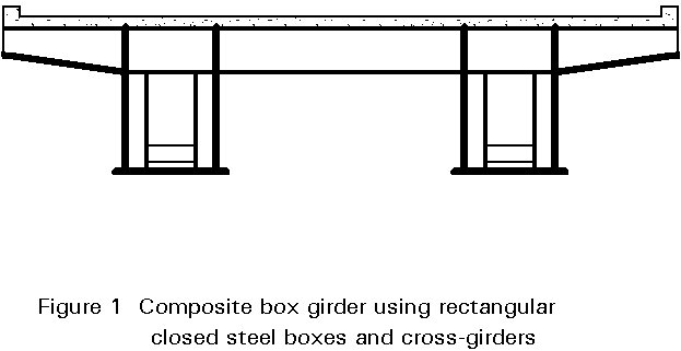
Box girders are used in building structures (Figure 1) as well as in bridges (Figure 2). In general, they are more expensive than plate girders because they require more time to make. They have, however, several advantages over plate girders which make their use attractive:
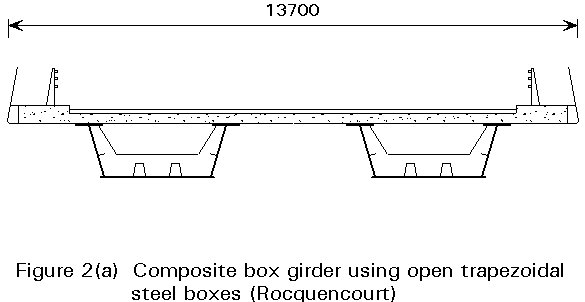
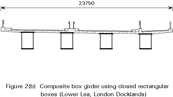
For bridges the two main types of cross-section are:
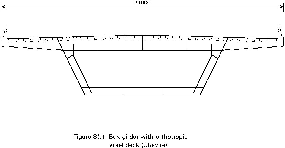
The box girder with an orthotropic deck is closed during all stages of erection (Figure 4). On the other hand, temporary horizontal bracing is generally provided between the webs of box girders with a top flange formed by a concrete deck slab until the concrete has hardened.
In the case of narrow box girders, the load bearing stiffeners can be located outside the box to increase stability (Figure 6).
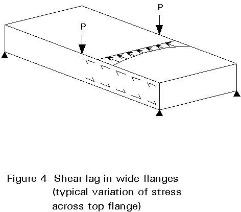
Special attention must be given to shear lag, distortion and warping stresses.
Depending on the features of the structure (short or long span, presence of horizontal curvature, etc.) different methods of analysis can be used, generally in the elastic range:
In very wide flanges, the shear lag effects, which are neglected in the global analysis, have to be taken into account for the verification of stresses, especially for short spans. The calculation is performed by means of an effective breadth which depends on the ratio of width to span.
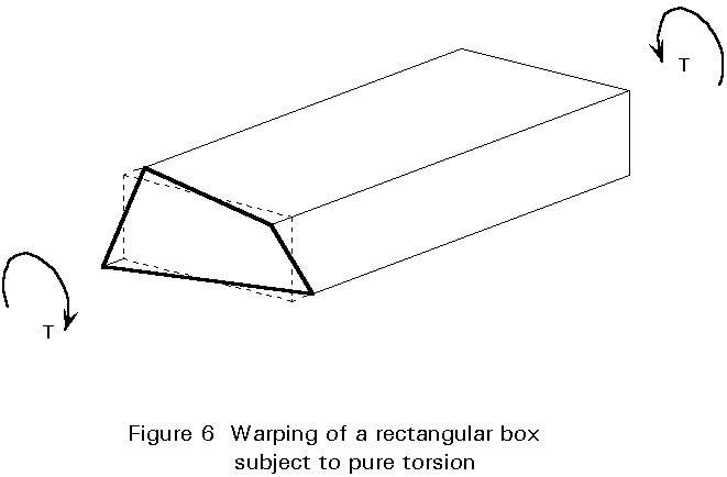
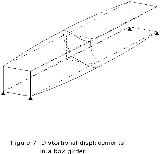
Torsional moments on the box girder tend to distort the cross-section. Intermediate diaphragms, spaced at suitable intervals, are necessary to prevent this distortion.
The warping stresses are in general very low but should be taken into account.
Most steel bridges have been designed using the linear theory of buckling (for example, Kloppel's charts). More advanced methods are now available which will be used in the future; two of these, the strut approach and the orthotropic approach, are covered in subsequent lectures.
The design of the longitudinal stiffeners can be by linear buckling theory or by the non-linear method. Torsional or local buckling is avoided by limiting the b/t ratios of the cross-section to class 3 or less when using the non-linear theory.
The transverse stiffeners should satisfy two criteria:
sc = st = 0
Torsion produces a shear flow in the box section. Each panel in the webs or flanges, is designed to resist this shear flow, generally using linear buckling theory.
Post-critical behaviour under torsion
The post-critical resistance is provided by diagonal bands in tension, in the flanges and webs. Figure 7 illustrates the tension field 1 and 1¢ ; due to the large flexibility of the horizontal panels, the width of this band is limited in comparison to that for the web of a plate girder. Moreover, equilibrium for a box girder length, between two diaphragms, requires compressive forces (see force 2, Figure 7) at the edges of the box girders. It is therefore advisable not use the post-critical reserve.
The main functions are:
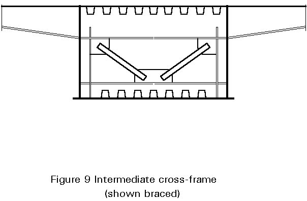
The main types of diaphragms are shown in Figure 2 (diaphragm with a man hole), Figure 3 (unbraced cross frames) and Figure 4 (braced cross frame).
For large deep box girders, intermediate diaphragms are generally unbraced or braced cross frames. An effective width of flange plate and web is taken into account when calculating stresses in the ring. Special attention is given to the design of the corners of the unbraced cross frame (which should resist the bending moments in the plane of the cross frame), and to possible eccentricities in the case of braced cross frames. When the intermediate diaphragm does not support traffic loads directly, it is, in general, lightly stressed.
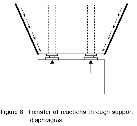
In addition to performing the different functions of intermediate diaphragms, the main purpose of support diaphragms is to transform the large support forces into shear flow along the web of the box section (Figure 5).
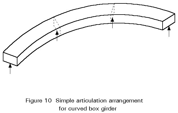
If a bridge consists of a single box girder, there are generally two supports at each end. Special attention has to be paid to any differential settlement between these two supports because of the inherently high torsional rigidity of the box girder. Single intermediate supports can sometimes be provided which also facilitate traffic flow under the bridge.
For large box sections, with large support forces, the use of a finite element program is recommended for the design of support diaphragms.
The detailing recommendations are essentially the same, whether linear or non-linear buckling theory is used.
General recommendations
LECTURES
Lecture 8.5.2: Page 8