ESDEP WG 11
CONNECTION DESIGN: STATIC LOADING
To review the behaviour and the basis for design of local elements in connections.
Lecture 1B.5: Introduction to Design of Industrial Buildings
Lecture 1B.7: Introduction to Design of Multi-Storey Buildings
Lecture 2.3: Engineering Properties of Metals
Lecture 2.4: Steel Grades and Qualities
Lecture 11.1.2: Introduction to Connection Design
Lectures 11.2: Welded Connections
Lectures 11.3: Bolted Connections
Lecture 11.4.1: Analysis of Connections: Basic Determination of Forces
Lecture 11.4.2: Analysis of Connections: Distribution of Forces in Groups of Bolts and Welds
Lecture 11.4.3: Analysis of Connections: Transfer of Direct Tension or Compression and Shear
Lecture 11.5: Simple Connections for Buildings
Lecture 11.6: Moment Connections for Continuous Framing
Lecture 11.7: Partial Strength Connections for Semi-Continuous Framing
This group of 4 lectures (11.4.1 - 11.4.4) explains how the behaviour of local elements in connections may be analysed so that each component may safely be proportioned to resist the loads it is required to transfer. It therefore develops the basic concepts of force transfer that were presented in general terms in Lecture 11.1.2.
This final lecture in concerned with the transfer of moments - particularly at beam to column connections. The moment is broken down into a localised tensile and a localised compressive force acting at a suitable lever arm so as to produce the couple that equates to the design moment. The need to consider also shear on the column zone immediately adjacent to the connection in the case of loading by unbalanced moments is also addressed.
The notation of Eurocode 3 [1] has been adopted.
The transfer of moment through a connection may best be appreciated by breaking the moment down into a pair of localised tensile and compressive forces acting at a suitable lever arm so as to produce a couple, see for example Figs. 2 and 3 of Lecture 11.4.1. The simplest form for this in a beam to column connection would be one in which only the beam's flanges are attached to the column so that one flange transmits tension, the other transmits compression and the lever arm is clearly the distance between flange centroids. (Any co-existing shear could, of course, be transferred through a web cleat or finplate arrangement of the sort illustrated in Fig. 17 of Lecture 11.4.3). The introduction of these localised forces into the column requires a careful consideration of the possible forms of failure and this topic is addressed in the first part of this lecture.
When the column is subject to unbalanced moment e.g. because a beam is present only on one side, then the moment(s) also produce a shearing effect on the panel of the column corresponding to the depth of the beam(s), see for example Fig. 3 of Lecture 11.4.1. This panel zone effect is considered in the second part of the lecture.
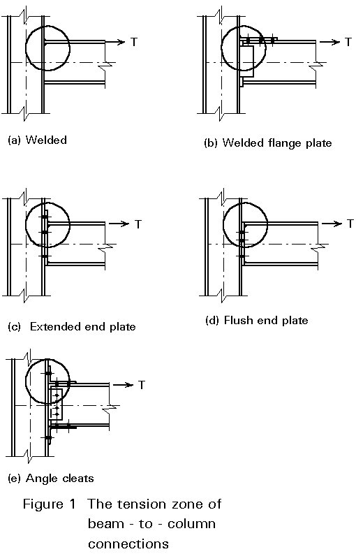
Figure 1 shows various forms of unstiffened beam-to-column connections intended to transfer moments. In the tension zone, marked with a circle, the tensile force must be transferred from the flange of the beam to the web of the column.

The size of the tensile force which can be transferred without stiffening the column depends on the resistance at this zone of the connection to a series of possible forms at failure. These possibilities are indicated in Figure 2 for welded connections and for bolted connections.
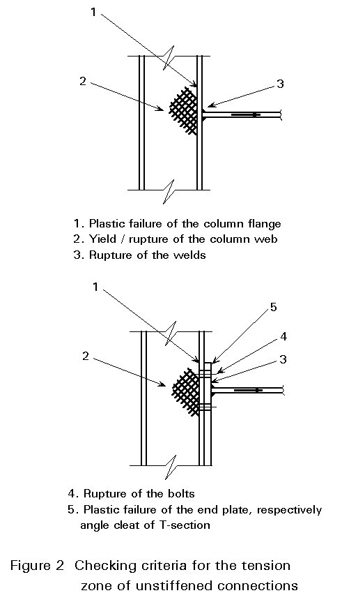
Design consists of recognising that 'the strength of the chain is determined by the weakest link'. For each of the potential failure possibilities, the design resistance T is calculated. Rules for these calculations are given in Annex J of Eurocode 3 [1]. The smallest of the calculated values for T controls.
The presentation in Annex J of Eurocode 3 is based on beam-to-column connections. However, several calculation rules are also applicable for other types of connections.
The calculation of the design resistance of the individual fasteners, welds and bolts, discussed in Lectures 11.2 and 11.3. Individual fasteners are covered by criteria 3 and 4 in Figure 2. The other criteria are discussed below. Possibilities for strengthening the connection and the design of such strengthened connections are also described.
A. Welded connection
Figure 3 shows a design model for a welded connection to a column flange.
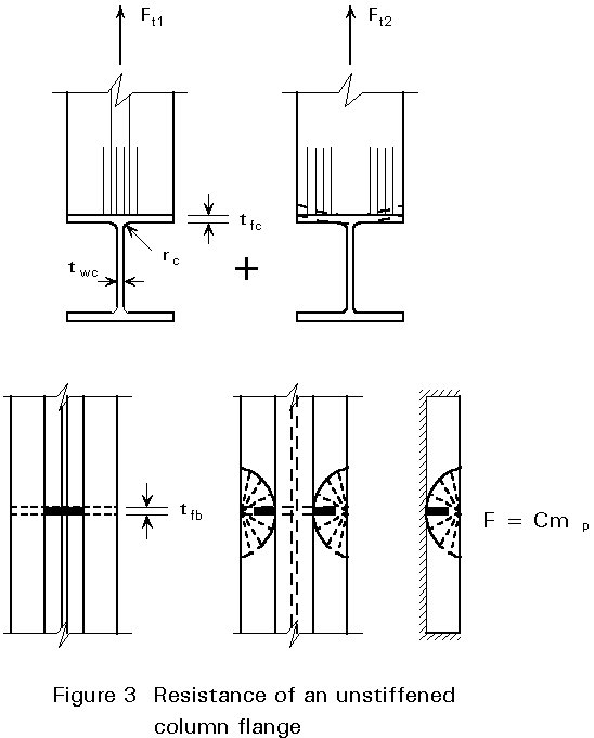
A part of the tensile force is transferred by direct normal stresses without bending the flange. The width of this part is twc+2rc. The tensile force through this part is:
Ftl = fyb . tfb (twc + 2 rc) (1-1)
The remaining part of the tensile force must be transferred via bending of the column flange to the web of the column.
For this load case a design model can be adopted, as indicated in Figure 3, based on a plate clamped at three edges with a line load in the middle.
Application of yield line theory gives a failure load that is proportional to the plastic moment resistance of the plate mp.
Ft2 = 2 C mp (1-2)
mp = ![]() fyc tfc2 (1-3)
fyc tfc2 (1-3)
Ft2 = 2 C ![]() fyc tfc2 (1-4)
fyc tfc2 (1-4)
The coefficient C is derived from tests [2]. A safe lower bound appears to be:
C = 14.
Therefore, the total design resistance of the unstiffened column flange follows from Equations (1-1) and (1-4):
Ft = fyb tfb (twc + 2 rc) + 7 fyc tfc2 (1-5)
or:
Ft = fyb tfb beff (1-6)
with:
beff = twc + 2 rc + 7 (fyc/fyb)(tfc2/tfb) (1-7)
This equation for beff is also discussed in Lecture 11.2.3.
Because of the limitations of the tests [3] which have been carried out to determine C, the effective width for the determination of Ft2 is limited to 7 tfc:
Ft £ fyb tfb (twc + 2 rc + 7 tfc) (1-8)
In order to provide sufficient deformation capacity, it is necessary that the flange of the beam yields before rupture of the weld or rupture of the flange of the column occurs. To obtain this behaviour the design resistance of the unstiffened column flange must be at least 70% of the yield force of the beam flange:
Ft ³ 0,7 Fy.bf = 0,7 fyb tfb bfb (1-9)
If this requirement is not fulfilled, then the connection must be strengthened by welded stiffening plates as indicated in Figure 4.
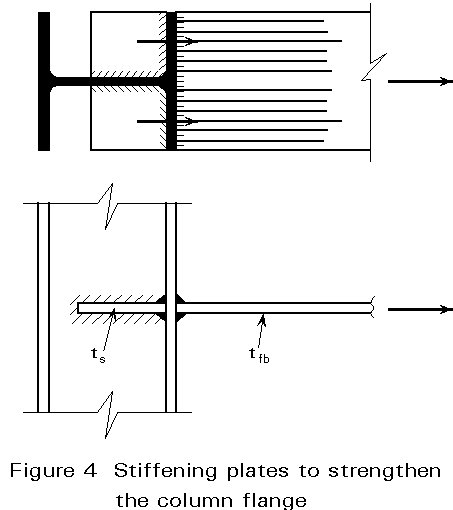
The application of short stiffening plates offers advantages during fabrication, because their dimensions do not need to correspond to the actual distance between the column flanges. The thickness and the steel grade of the stiffening plates are normally chosen to be equal to those of the beam flange.
B. Bolted connection
In contrast to the situation for a welded connection, when using a bolted arrangement the total tensile force to be transferred via the column flange causes only bending moments (no direct load transfer), see Figure 5.
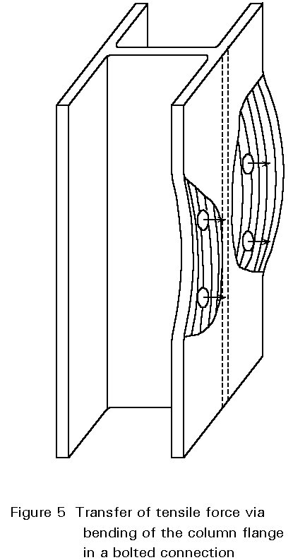
To gain insight into the various forces present in this type of connection, it is useful to consider first a more simple case. Two T-stubs are chosen, connected by two bolts and loaded by a tensile force Ft, see Figure 6.
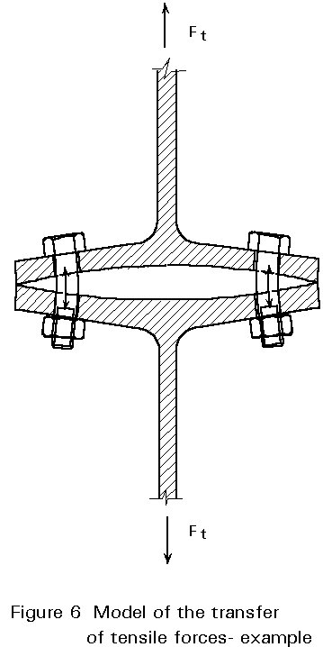
Initially, it is assumed that the force in each bolt is 0,5 Ft and that the flange is designed to transfer these bolt forces via bending, see Figure 7. The necessary thickness tf follows from:
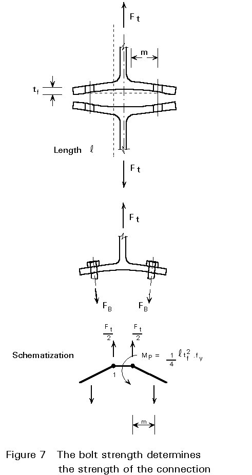
FB = 0,5 Ft (1-10)
0,5 Ft . m = Mpl (1-11)
Ft = ![]() (1-12)
(1-12)
ft =  (1-13)
Ft = ![]() (1-14)
(1-14)
tf =  (1-15)
In the above Equations, the dimensions of the bolts and the flange are such that the tensile resistance of the bolts governs the strength of the connection. At the onset of failure, the flanges separate from each other over the entire area.
If the bolts are chosen to be stronger, then the ultimate tensile force increases above the value given in Equation (1-14). With stronger bolts the flanges of the T-stubs yield, while the bolt deformation is reduced, see Figure 8.
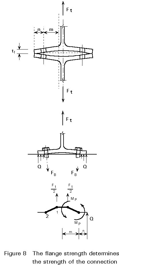
Now at the onset of failure the flanges do not separate over the entire area, but contact forces develop at the edges. These contact forces are called prying forces. These prying forces produce an extra bending moment in the flanges. When the prying forces are sufficiently large, this bending moment is equal to the plastic moment mpl. In this situation four yield lines are present.
The following analysis can now be carried out:
0,5 Ft . m = 2 Mpl (1-16)
Ft = ![]() (1-17)
(1-17)
Ft =  (1-18)
Ft = ![]() (1-19)
(1-19)
tf = √(Ftm/lfy) (1-20)
Q = ![]() (1-21)
(1-21)
Q = ![]() (1-22)
(1-22)
Ft + 2 Q = S FB = S Ft.u (1-23)
Ft + 0,5 ![]() Ft = S Ft.u (1-24)
Ft = S Ft.u (1-24)
with:
g = ![]() (1-25)
(1-25)
it follows:
Ft = ![]() (1-26)
(1-26)
Between the two extremes (Figures 7 and 8), there is an intermediate case where prying forces are present, but where the bolts rupture before the mechanism in the flanges with four yield lines has fully developed.
With the aid of the above Equations, a diagram can be drawn showing the relation between plate strength and bolt strength and the accompanying failure modes, see Figure 9. In Figure 9, g and b have the following meaning:
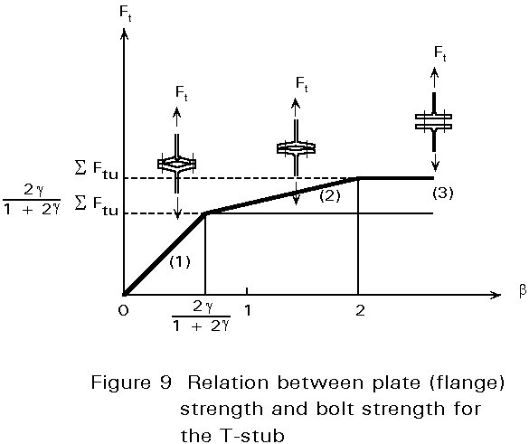
g = ![]() but g £ 1,25 (1-27)
but g £ 1,25 (1-27)
b = ![]() (1-28)
(1-28)
It is recommended the connection is designed such that failure mode (1) just controls, b = 2g /(1 + 2g), because then the deformation capacity is provided in the best way and the bolt strength is consistent with the flange strength (m). In failure mode (3) the deformation arises mainly from the bolt elongations. These deformations are small compared with the plastic deformations of the flanges in failure mode (1). The deformation capacity of failure modes (2) and (3) can be increased by selecting bolts with threads over the entire length of the bolt.
According to Annex H of Eurocode 3 [1], the tension zone of an unstiffened column flange should be assumed to act as a series of equivalent T-stubs with a total length equal to the total effective length S leff of the bolt pattern in the tension zone of the connection.
Using yield line theory, the effective length leff appropriate for each of those T-stubs may be calculated, see Figures 10 and 11.
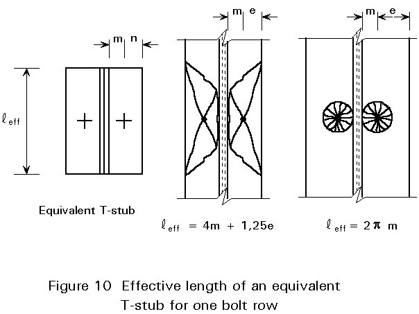
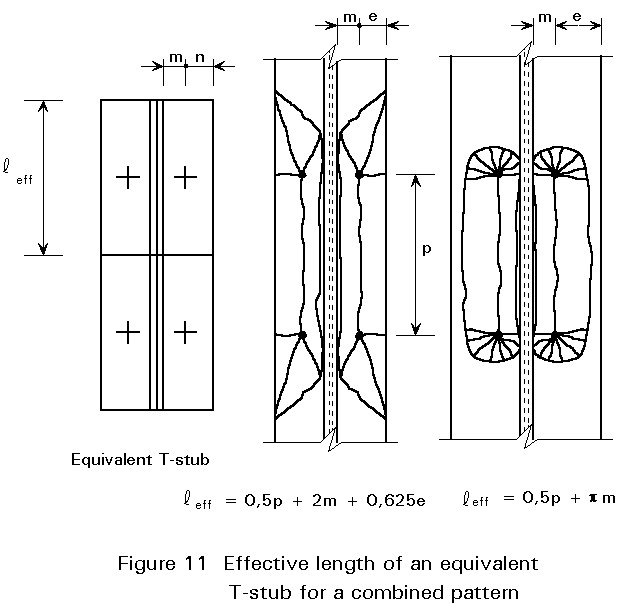
If the distance between the bolt rows is large, then a separate yield line pattern around every bolt is formed, see Figure 10.
The circle pattern governs if e is large with respect to m, i.e.
if e > 1,8 m (1-29)
The values for leff are:
leff = 4 m + 1,25 e (1-30)
leff = 2 pm (1-31)
leff = 0,5 p + 2 m + 0,625 e (1-32)
leff = 0,5 p + pm (1-33)
In contrast to welded connections, it is possible when using bolted connections to strengthen the connection with stiffening plates such that the force can be transferred from the beam flange into the column web without bending of the former, Figure 12.
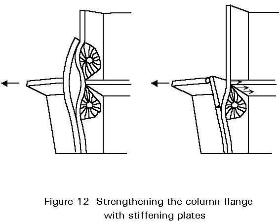
If stiffening plates are used, the stiffness and strength of the column flange is increased. The increase is beneficial for the design strength of the bolt rows near such stiffening plates.
The strength of such bolt rows can be calculated by introducing a T-stub with an equivalent length leff.
According to Annex J of Eurocode 3, the value of leff equals:
leff = a m1 (1-34)
Values for a are given in Figure 13. This diagram is established on the basis of yield line theory and test results [4]. The value of a depends on the geometry near the stiffening plate.
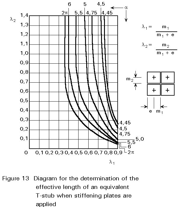
In the equation for l1 and l2 (the values on the horizontal and the vertical axes in Figure 13), m1 is the distance between the bolt and the column web, and m2 is the distance between the bolt and the stiffening plate.
Alternatively the column flange may be strengthened by using loose backing plates as indicated in Figure 14.
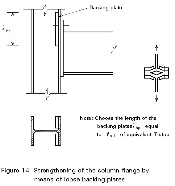
The length of the backing plates should be at least the length of leff for the bolt pattern considered.
The backing plates increase the plastic moment on the yield line through the bolts, but not the plastic moment at the junction of the flange with the web, see Figures 7 and 8.
Clearly backing plates are only effective if failure mode (1) in Figure 9 is decisive, see also Figure 8.
Equation (1-17) can be modified to account for the extra yield line:
Ft = ![]() (1-35)
(1-35)
Ft =  (1-36)
Ft = ![]() (1-37)
(1-37)
It should be noted that, because of the appearance of only one yield line, a factor 2 must be used for 2 Mp.bp in Equation (1-35).
From the above Equations, it may be concluded that, if tf = tbp, the use of backing plates gives an increase of 50% in the design resistance of the column flange.
The force Ft spreads in the column web over a length beff, see Figure 15.
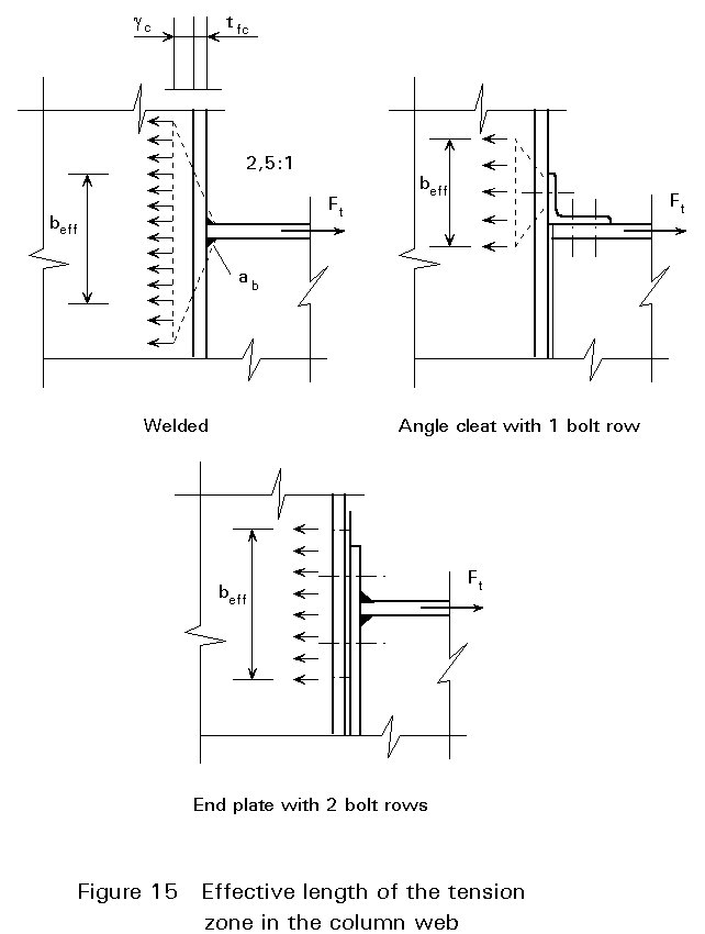
It is assumed that the failure load is reached if the average stress due to Ft over the length beff equals the yield stress:
Ft = fyc twc beff (1-38)
For a welded connection, the same expression for beff is used in the tension zone as in the compression zone. Although tests [5] have shown that the strength in the tension zone is usually greater than in the compression zone, the same equation is chosen for reasons of simplicity.
According to Eurocode 3, beff for a welded connection is given by:
beff = tfb + 2 ![]() ab + 5 (tfc + rc) (1-39)
ab + 5 (tfc + rc) (1-39)
For a bolted connection, the effective length of the column web in the tension zone is taken equal to the total effective length of the equivalent T-stubs (see Section 1.2).
The column web can be strengthened by stiffening plates and/or by welded supplementary web plates, see Figure 16.
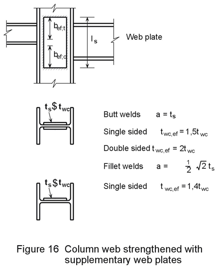
If the web plate is only single sided and is connected by butt welds, only half of the plate thickness may be used for the calculation of the design resistance. The reasons are the eccentricity and the design of the welds. If fillet welds are present, some spaces must be left between the flange and the edge of the plate to permit a reasonable execution of the weld. For this reason, the force must be transferred through initially the thickness of the web. Therefore, the effective thickness of the combined column web and supplementary web plate should not be taken greater than 1,4 times the web thickness (1,4 twc).
The action of a compression force on an unstiffened column may cause local buckling of the column web. Using tests on special test specimens [5], as shown in Figure 17, and on complete beam-to-column connections, research has been carried out to establish a design model. The derived model is that the column web starts buckling if the average stress over a certain effective length equals the yield stress. This model, therefore, is basically the same as the model for the transfer of a tensile force in the web, as discussed above.
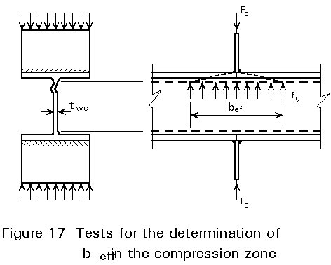
Fc = fyc twc beff (2-1)
In Figure 18 the equations for beff are given which apply for various designs of the compression zone. The basic assumption in these equations is that the spread in the column flange and the column radius have a slope 2,5 : 1, and the slope in other parts of the connection is 1 : 1.
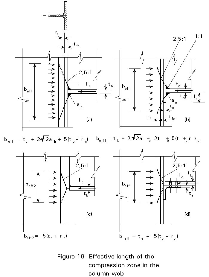
In the model of Figure 18b and Figure 19 with the extended end plate, it is assumed that the end plate under the beam flange yields before the buckling load in the column web is reached. In this case, the compression force Fc spreads over the thickness of the end plate.
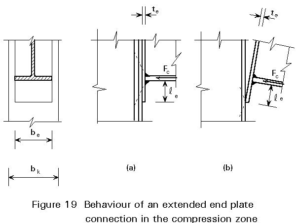
The projection of the end plate should obey the following condition:
fy Wpl.endplate £ Fc le (2-2)
fy ![]() bp tp2 £ Fc le (2-3)
bp tp2 £ Fc le (2-3)
le ³ ![]() (2-4)
(2-4)
If the condition of Equation (2-4) is not fulfilled, then a hard point is formed at the edge of the end plate. The effective length beff is then smaller:
beff = 5 (tc + rc) (2-5)
The moment arm, however, between the tensile force in the tension zone and the compression force is somewhat greater. This is an advantage.
In the case of large axial forces in the column, the local buckling load in the compression zone is reduced. As long as the axial stress sn is smaller than 0,5 fy, the influence can be ignored. For greater values of sn, the design resistance for the compression force Fc should be calculated with the following equation:
Fc = fyc twc beff [1,25 - 0,5sn / fyc] (2-6)
In this equation the second part is the reduction factor:
R = 1,25 - 0,5 [sn / fyc] but R £ 1,0 (2-7)
The column can also be strengthened in the compression zone with stiffening plates between the flanges or with a supplementary web plate.
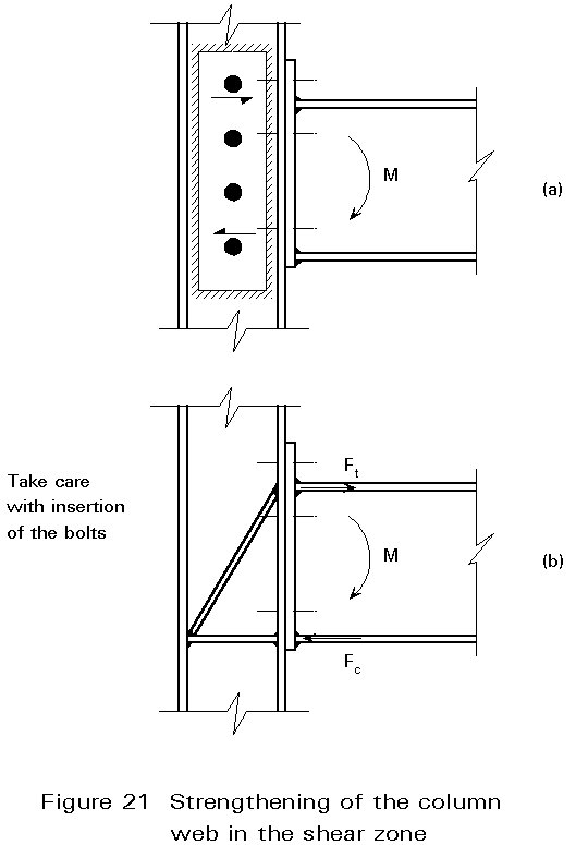
In non-symmetric connections, such as T- and corner connections, the column web is also loaded by a shear force Fv. Loading by a shear force also occurs in symmetric connections that are loaded asymmetrically.
For instance in the T-connection of Figure 20, the tensile force in the upper flange of the beam must be transferred through the shear panel to be in equilibrium with the compression force in the lower flange of the beam.
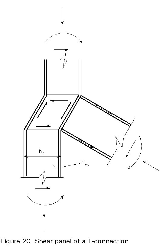
Assuming that the web is sufficiently stocky for shear buckling not to occur, the design resistance of the shear panel is:
Fv = ![]() hc twc (3-1)
hc twc (3-1)
The column web can be strengthened with diagonal plates or with one or two supplementary web plates, see Figure 21. When diagonal plates are designed, care should be taken to avoid problems with the installation of the bolts; see for example Figure 21b.
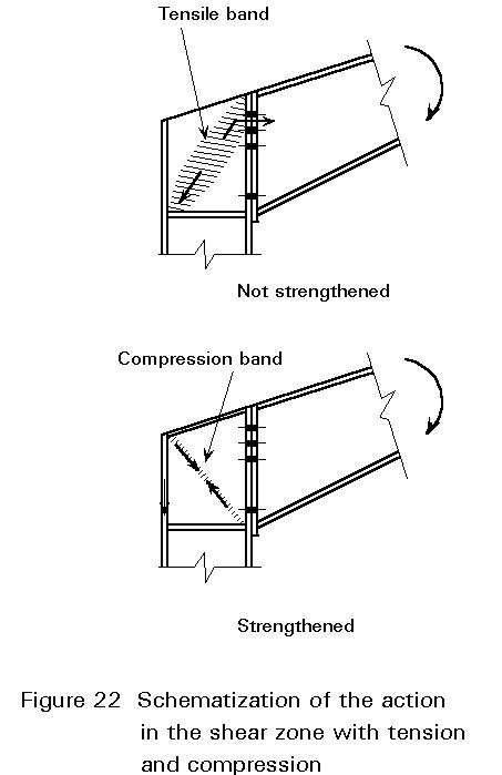
The action of stiffeners sometimes can be better understood when thinking in terms of tension and compression; see for example the arrangement in Figure 22.
[1] Eurocode 3: Design of Steel Structures: European Prestandard 1993-1-1: Part 1.1: General rules and rules for buildings, CEN, 1992.
[2] Wood, R. H., "Yield Line Theory", Research Paper nr. 22, Building Research Station, Watford, England, 1955.
[3] Zoetemeijer, P., Summary of the research on bolted beam-to-column connections, Delft University of Technology, Faculty of Civil Engineering, Stevin Laboratory report 6-90-02, 1990. This report is also published as a background report for Eurocode 3, Chapter 6.
[4] WRC and ASCE, "Commentary on Plastic Design in Steel", Progress Report 6: Connections, Journal Eng. Mech, Div., ASCE, 86, EM2, April 1960, pp 107-140.
[5] Graham, J. D., Sherbourne, A. N., Khabbaz, R. N., and Jensen, C. D., Welded Interior Beam-to-Column Connections, Welding Research Council Bulletin nr 63, August 1960.