ESDEP WG 10
COMPOSITE CONSTRUCTION
To describe the design of one-way spanning composite slabs, formed using profiled steel sheeting and a concrete topping, including consideration of ultimate and serviceability limit state design according to Eurocode 4: Part 1 [1] for building structures.
Lecture 9.1: Thin-walled Members and Sheeting
Lecture 10.1: Composite Construction - General
Lecture 10.6.1: Shear Connection I
All other lectures in Group 10.
Worked Example 10.4: Design of a Composite Slab
Descriptions of composite slabs, typical profiled sheeting and means of ensuring composite behaviour are given. Design criteria are identified in terms of loads, design resistance and serviceability limits. Analysis of continuous slabs is based on elastic or plastic theories. The resistances of critical cross-sections are calculated considering all possible modes of failure. The design for the ultimate limit state design consists of checking that slab resistance is sufficient to withstand maximum predicted forces; design for the serviceability limit state is performed to limit concrete cracking and slab deflections, taking into account creep and shrinkage of the concrete. The above methods are illustrated by Worked Example 10.4.
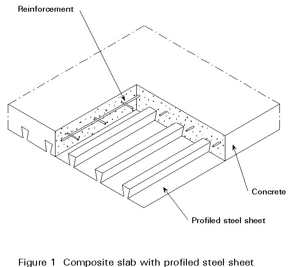
A composite slab consists of a cold-formed profiled steel sheet covered with a concrete slab containing reinforcement (Figure 1). Such slabs are generally used in frame structures, with steel floor beams, as discussed previously in Lecture 10.1. They can also be used in combination with other materials.

In this type of construction the profiled sheet has several functions:
The present lecture is mainly concerned with composite slabs when the steel-concrete bond has been formed, i.e. after hardening of the concrete. Design for the construction stage, when the profiled steel sheet supports the weight of wet concrete, is only considered briefly.
There are many types of profiled sheet used for the construction of composite slabs (Figure 2). These types vary in form, rib depth, rib spacing, sheet size, style of lateral over-lapping; in the methods of stiffening the flat elements of the profile; and in the methods of mechanical connection which ensure bond between the steel sheet and concrete slab.
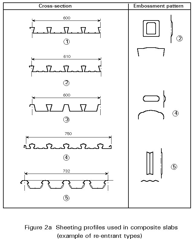
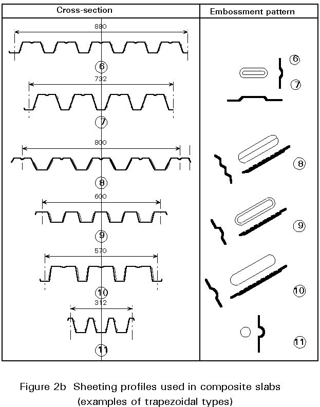
The thickness of the sheets can vary from 0,75 mm to 1,5 mm but in normal practice it lies between 0,75 and 1,0 mm.
The height of the profiled sheets can vary from 38 mm to 80 mm.
Whatever the particular requirements for a steel framed building, it is probable that they can be met by using a profiled sheet from this range, as the typical criteria for sound insulation, fire protection, maximum span and maximum load can easily be met.
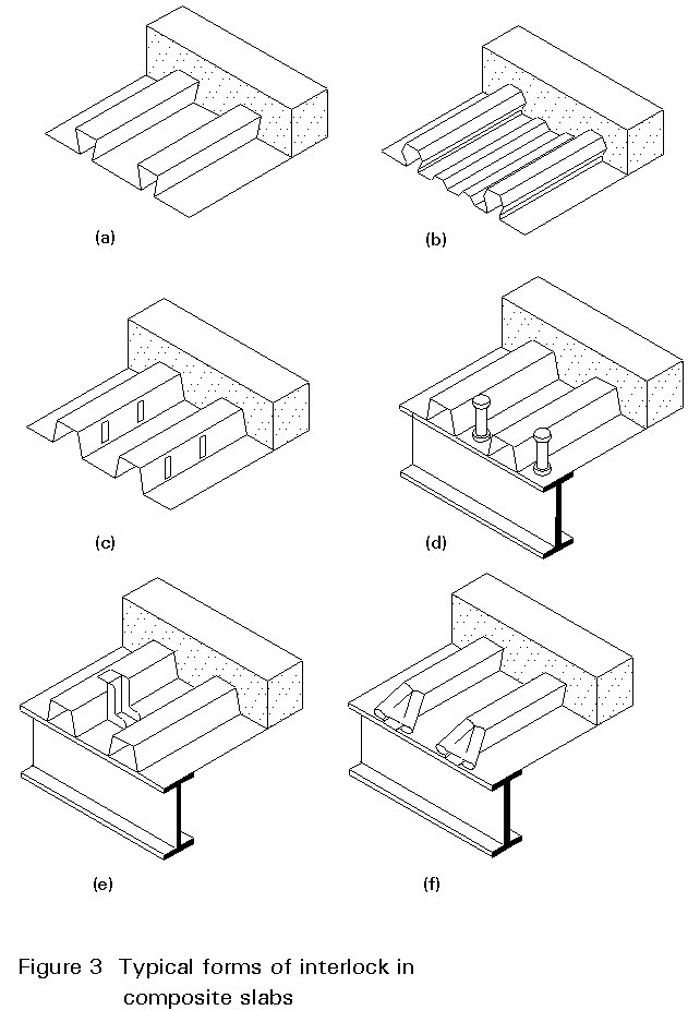
The bond between the concrete slab and the profiled sheet must be capable of transmitting longitudinal shear at the steel-concrete interface.
This connection can be made in one or more of the following ways, as shown in Figure 3 (which has been taken from Fig. 7.1 of Eurocode 4 [1]):
When designing composite slabs two distinct structural states must be checked: firstly, the temporary state of execution, when only the sheeting resists the applied loads; secondly, the permanent state, after the concrete is bonded to the steel giving composite action.
Relevant limit states and load cases are considered for both design situations.
a) Profiled sheeting as shuttering
Verifications at the ultimate limit state and the serviceability limit state are required, with respect to the safety and serviceability of the profiled sheeting acting as formwork for the wet concrete. The effects of any temporary props used during execution, must be taken into account in this design situation.
b) Composite slabs
Verifications at the ultimate limit state and the serviceability limit state are required, with respect to the safety and the serviceability of the composite slab after composite behaviour has commenced and any props have been removed.
The loads and other actions to be considered, for the ultimate and serviceability limit state, are given in the relevant Eurocodes.
For the situation where the profiled sheeting acts as formwork, the following loads should be considered in the calculations, taking into account any propping effects:
The execution loads represent the weight of the operatives, any loads due to placing the concrete, and also take into account any impact or vibration likely to occur during execution. In accordance with Eurocode 4 [1], a representative value of execution loads (including any excess of concrete) can be taken to be 1,5kN/m2, distributed on an area 3m x 3m (or the span of the sheeting, if less) and 0,75kN/m2 on the remaining formwork surface.
For the situation where the steel and the concrete act compositely, the loads acting on the slab should comply with Eurocode 1 [2].
For the serviceability limit state, long duration values of the loads are required for the calculation of deformations taking into account creep and shrinkage of the concrete.
Profiled sheeting
Steel used for the fabrication of profiled sheeting has a minimum nominal yield strength of 220N/mm2. In general, however, composite slabs are fabricated from profiled steel sheeting manufactured from galvanised steel of grades 280 to 350, according to European Standard pr EN 10147 [3]. The respective nominal values of yield strength for these steels are:
Steel grade 280 : fyb = 280 N/mm2
Steel grade 350 : fyb = 350 N/mm2
The characteristic yield strength fyap, is equal to the nominal yield strength of the basic material fyb quoted above for calculating ultimate resistance.
Concrete
Concrete used for composite slabs can be made with normal or lightweight aggregate.
The most commonly used grades of concrete (grading according to Eurocode 2 [4]) are given in Table 1, which also gives the following properties: characteristic cylinder 28 days compressive strength, fck; mean tensile strength, fctm, which is associated with the shear strength tRd; and the secant modulus of elasticity, Ecm.
Reinforcement
All reinforcing steels used in composite slabs should conform to the requirements of Eurocode 2 [4]. The types concerned are essentially ribbed bars and ribbed wires, including welded mesh, fabricated from steels of classes of ductility A or B. Class A is recommended for negative moment reinforcement and fire resistance reinforcement.
Characteristic values for the most commonly used reinforcing steels are given in Table 2.
a) Deflection during execution (construction stage)
During execution, deflection of the profiled sheeting under loads due to self-weight and wet concrete, must not exceed a limiting value.
For example, Eurocode 4 [1], sets this limit at l/180 or 20 mm, where l is the span of the sheeting between supports. In the case of propped profiled sheeting, props are considered as supports. In situations where greater deflection can be tolerated, calculation for the ultimate limit state should take into account the weight of additional concrete due to the deflection (the "ponding" effect).
b) Deflection in the composite state (permanent state)
Deflections in the composite state must be limited, in order that the slab may fulfil its intended function and that any other elements in contact with it (false ceilings, pipework, screens, partitions) will not be damaged. Deflection limits should, therefore, be considered relative to the use of the slab, the execution procedure and architectural aspects (aesthetics).
The values recommended by Eurocode 3 [5], for floors and roofs in buildings, are as follows:
dmax £ l/250
(l is the span of the composite slab)
d2 £ l/300
where
d
max is the total deflection of the floor or roof, including any pre-camber and any variation of the deflection due to the permanent loads immediately after loading, and including d2.d
2 is the variation of the deflection due to variable loading acting on the slab plus any time-dependent deformations due to the permanent loads.If the composite slab supports brittle elements (cement floor finishes, non-flexible partitions, etc), d2 must be limited to l/350.
Two verifications are necessary to ensure that safety and serviceability requirements are met:
a) Verification conditions for the ultimate limit states
The resistance of the profiled sheeting (execution stage) or the composite slab (permanent state) must be sufficient to resist the exterior loads. Each section or member must be capable of resisting the internal forces determined by the analysis of the structure.
When considering a limit state of rupture or excessive deformation, it shall be verified that
Sd £ Rd
where
Sd is the design value of load effects
Rd is the design value of the resistance
The load combinations required for design, and the calculation of their effects (moments, shears, etc.) are not discussed in this lecture; for further information reference should be made to the relevant Eurocodes or to National Codes.
Calculation of the resistance of critical sections of composite slabs is given in Section 4.
b) Verification conditions for the serviceability limit states
The behaviour of the profiled sheeting, under its self-weight and the weight of the wet concrete, must fall within accepted limits.
The following verifications should be made:
The behaviour of the composite slab under permanent loads and variable service loads must fall within accepted limits.
The following states should be verified:
During execution when the concrete is wet, the profiled sheeting alone resists the exterior loads. Its behaviour is then comparable to the behaviour of profiles used for roof decking.
The profiled sheeting is subjected mainly to bending and shear; compression due to bending may arise in either the flanges or the web; shear occurs essentially near the supports. The thin-plate elements, which make up the profiled sheeting, may buckle prior to yield under these compressive and shear stresses, thereby reducing the resistance and stiffness of the sheeting.
Current design procedures rely on the concept of effective width, as described in Lecture 9.1, to provide a method for the calculation for this type of thin-walled member. Clearly, the effective width of the compression flange depends upon the maximum stress imposed on the flange, which in turn depends on the location of the neutral axis of the cross-section. As the ineffective area of the flange increases under increasing bending moment, the neutral axis of the profile is lowered and the extreme fibre stresses change accordingly. Iterative design calculations, therefore, become necessary both for resistance and deflection.
The behaviour of composite slabs is somewhat different from that of other similar forms of composite construction, such as reinforced concrete slabs or composite beams of steel and concrete. Composite action is achieved in reinforced concrete by the bond of the concrete to the reinforcement due to the special profile of the bars used. This bond, verified by tests, is the same as the ultimate resistance of the reinforcement in tension assuming always that the slab can develop full resistance to bending. In composite beams, composite action is achieved by connectors fixed to the top flange of the steel beam. The design of these connectors may be based on the assumption that the beam attains ultimate bending resistance (full connection). If the number of connectors is smaller than that required for full connection then the connection is partial. In this case the ultimate resistance to bending depends essentially on the number of connectors, the slope of the load-slip diagram for the connectors, the span of the beam, and the method of construction, i.e. execution.
The composite slab with profiled sheeting is half-way between these two systems. On the one hand sheeting with embossments or anchorages is comparable to reinforcement, whereas, on the other hand, sheeting is an element with bending rigidity similar to steel beams. The difference results from the fact that profiled sheeting, and similarly the embossments, can be deformed under load. Also, unlike reinforcement, profiled sheeting does not benefit from being totally embedded in concrete. The numerous parameters involved, therefore, make the analysis of the actual behaviour of composite slabs very complicated.
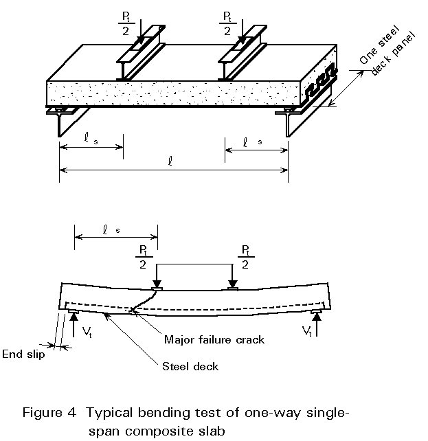
Recent theoretical and experimental studies have identified different parameters and revealed two behaviour modes. These modes are based on the analysis of load-deflection curves which can be obtained, for example, when bending tests are performed on composite slabs on two supports subjected to two concentrated loads (Figure 4).
Mode 1
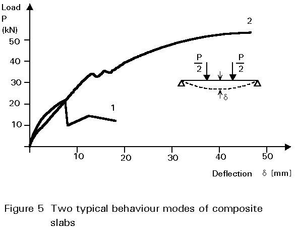
The characteristic of this mode is an initial linear curve, as in Figure 5, which corresponds to the behaviour of a homogeneous material held together by surface effects (chemical bond and friction) and mechanical effects (embossments and anchorages). No significant relative slip between the steel and the concrete takes place; as the load increases, the rigidity decreases because of the cracks which form in the concrete in tension. Shear stresses between the steel and concrete increase in the zone between the concentrated load and the support. At a certain point the relative slip is such that the bond is broken and the load suddenly decreases. All the shear force must therefore be taken up by friction and by any embossments; the amount of load decrease is therefore dependent on the quality of the mechanical bond. With further deformation of the slab the load increases again slightly without ever reaching the level of the initial phase. This means that the mechanical bond is incapable of achieving a composite effect superior to that of simple surface bond. It should be noted that the decrease in the load is not due to the sudden opening of tension cracks in the concrete, because this is prevented by the sheeting, but by relative slip between the concrete and the sheeting.
Mode 2
This mode is characterised by an initial phase similar to that of mode 1. However, the second phase is different: after a decrease in load, corresponding to failure of the steel-concrete bond in the sheared zone, the load increases again up to a higher level. This increase shows that the mechanical connection is capable of transferring the shear force until failure occurs by bending, corresponding to full shear connection, or by longitudinal shear, corresponding to partial shear connection.
The two modes described above represent brittle (or non-ductile) behaviour (mode1), and ductile behaviour (mode 2), see Figure 5.
The analysis of a composite slab may be made in accordance with one of the following methods:
a) Analysis for the ultimate limit states
In most cases analysis of composite slabs, continuous over several spans, is performed according to the elastic method, for a slab of unit width (1m), comparable to a beam of constant inertia (Figure 6, line (1)). The assumed inertia is that of the uncracked section.
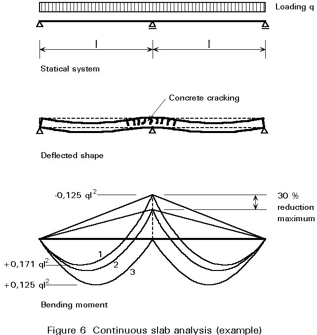
It is possible to take concrete cracking into account in several ways:
The analysis will use one of the above statical models in conjunction with the design loads determined, as discussed earlier in Section 2.2.
Worked Example 10.4 illustrates how the actual stresses and strains are determined and how the internal forces and moments (M, N, V) are calculated for the structural system chosen.
b) Analysis for the serviceability limit states
An analysis of the composite slab, for calculating deflection, may be made with the following assumptions:
Possible slip between the profiled sheeting and concrete slab must be taken into account at the serviceability limit states. Slip may occur in the span and greatly influence deflection. It is necessary, therefore, to fully understand the behaviour of composite slabs through approved testing.
To eliminate excessive slip it is possible to place anchorages, for example welded studs or shot-fired connectors, at the ends of the spans (see Figure 3d and e).
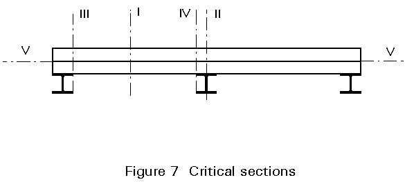
According to Section 3, the critical sections which should be verified, are as follows (Figure 7):
The ultimate moment of resistance of a section, Mpc, may be determined by assuming a plastic distribution of stresses (Figure 8). For an under-reinforced* section, the position of the plastic neutral axis is given by:
x = [Aap.fyap/gap]/[b.0,85fck/gc] (1)
where:
Aap is the area of the profiled sheet section.
fyap is the characteristic yield strength of the sheet steel.
g
ap is the partial safety factor for steel sheeting.b is the width of the slab (b = 1000 mm).
fck is the characteristic compressive strength of the concrete.
g
c is the partial safety factor for concrete.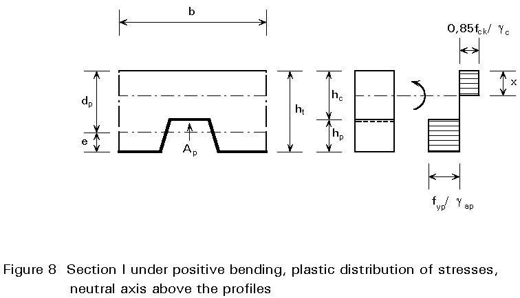
If the neutral axis is situated above the profiles of the sheeting (x £ hc) the design positive bending resistance has the value:
M+p,Rd = Aap.fyap[dc - x/2]/gap (2)
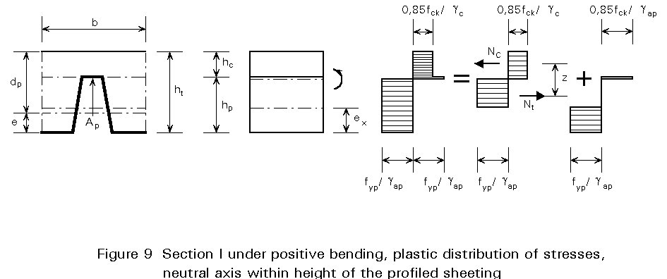
All commonly used profiled sheeting (ha £ 60 mm), in conjunction with a concrete slab of minimum thickness hc = 50 mm, have a plastic neutral axis situated above the profiles. For deeper sheets, the neutral axis may be situated within the height of the profiled sheeting.
In this case, the positive bending resistance of a section may be calculated as follows, by neglecting the concrete in the troughs (Figure 9):
M+p,Rd = Mcz+ + Mpa,r (3)
z+ = ht - dc/2 - ep + (ep - e)Nc/[Aap.fyap/gap] (4)
Nc = hc.0,85fck/gc (5)
Mpa,r = 1,25Mpa [1 - Nc/(Aap.fyap/gap)] £ Mpa (6)
where
e is the distance from the centroid of the effective area of the sheeting to its underside.
ep is the distance from the plastic neutral axis of the effective area of sheeting to its underside.
Mpa is the plastic moment resistance of the effective cross-section of the sheeting.
The section of a continuous composite slab at a support can be compared to a reinforced concrete section. As a simplification, the contribution of the profiled sheet is neglected. The design section and the distribution of stresses at the ultimate limit state are shown in Figure 10.
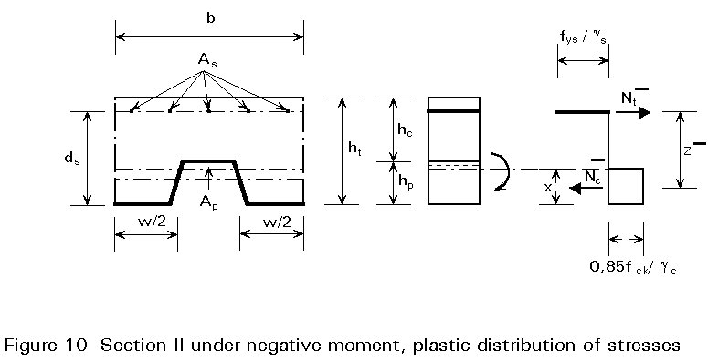
The design negative bending resistance is given by yielding of the reinforcement at the support (under-reinforced slab):
M+p,Rd = As.fysz-/gs (7)
where
As is the area of reinforcement
fys is the yield strength of the reinforcement
g
s is the partial safety factor for the reinforcementz- is the lever-arm of the internal forces Nc and Nt.
The condition of equilibrium between these forces allows the determination of z-:
Nc- = bcx0,85fck/gc= As.fys/gs= Nt- (8)
x = [As.fys/gs][bc0,85fck/gc] (9)
![]() = d¢s - x/2 (10)
= d¢s - x/2 (10)
where
bc is the width of the concrete in compression, taken as the width of the troughs over 1m for simplicity (bc = ebo).
d¢s is the effective depth
In general the vertical and the punching shear resistances are assumed to be given by the concrete section since the contribution of the steel sheeting is neglected.
The vertical shear design resistance, over a width equal to the distance between centres of ribs has the value:
Vv,Rd = bo ds tc (11)
where
t
c is the limiting shear stress appropriate for composite slabs (gc included).t
c = tRd k1 k2where
k1 = 1,6 - ds ³ 1,0 (ds in m)
k2 = 1,2 + 40 po
r
o = As/bo ds < 0,02As is the area of reinforcement in tension provided in order to distribute cracking. In positive bending regions, As is to be replaced by Aap.
t
Rd is the basic shear strength (see Table 1).The punching shear resistance Vp,Rd of a composite slab at a concentrated load should be determined from:
Vp,Rd = Cp hc tc (12)
where
Cp is the critical perimeter determined as shown in Figure 11.
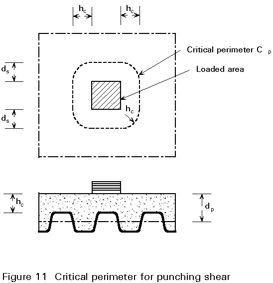
hc is the thickness of the concrete slab (above the ribs).
t
c is the limiting shear stress given above.Resistance to longitudinal shear in composite slabs is due to the steel-concrete bond at the interface of these two materials, established by friction, embossments or connectors placed at the ends of the spans (see Section 3). The ultimate resistance of these connections can only be determined by testing, as described in Section 10.3 of Eurocode 4 [1].
a) Empirical "m-k" method
The most commonly used method for calculating ultimate longitudinal shear was developed in the United States [6]. This method is used in many codes of practice, including Eurocode 4. It is based on at least six tests of simply supported composite slabs, which determine two coefficients m and k (see Figure 12), for the test profile.
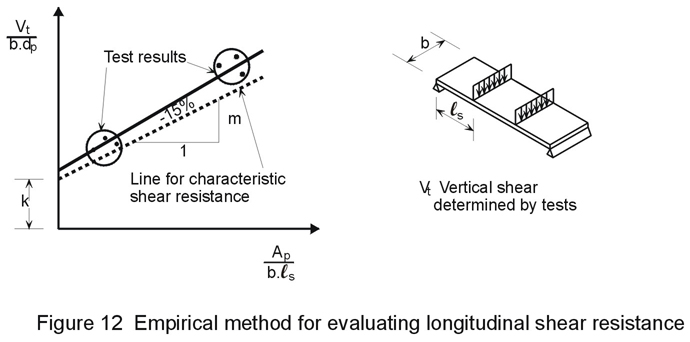
The longitudinal shear resistance of a composite slab, consisting of the same type of profiled sheet as that tested, is then given by the following maximum design vertical shear:
Vl,Rd = bds[(mAsp/bls) + k]/gvs (13)
where
ls is the shear span.
g
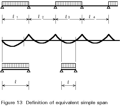
vs is the appropriate partial safety factor for longitudinal shear only.For a uniformly loaded slab, ls = l/4; for simply supported beams, l is the span, whereas for continuous beams l is the equivalent simple span between points of contraflexure; for end spans, the full exterior span length is used in design (see Figure 13 which has been taken from Fig. 7.10 of Eurocode 4 [1]).
If the connection provided by friction (due to the rib shape) or by embossments is not sufficient, it is possible to place anchorages (generally steel-concrete connectors) at the ends of the span.
The ultimate resistance of such anchorages is generally governed by the pull-out resistance of the sheet. For a stud, this resistance is given by the following expression:
Nt,ap = k3 dw t fyap/gap (14)
k3 = 1 + a/dw £ 4,0
where
dw is the diameter of weld around the stud.
a is the distance between the axis of the stud and the extremity of the profiled sheet (a ³ 2dw).
b) Partial shear connection method
The fact that composite slabs fail by longitudinal shear in most cases, allows this structural system to be compared to a composite steel beam and concrete slab with partial shear connection. It is also possible to represent the resistance of such slabs by a diagram giving MSd/MRd as a function of Nc/Ncf. This diagram is different to that given for composite beams due to the fact that the degree of partial shear connection Nc/Ncf is not a function of the number of connectors, but of the shear length ls and of the distribution of longitudinal shear stresses t over this length. The relative slip s between the profiled sheeting and the concrete also plays a more important role.
The determination of such diagrams for design is therefore complicated since one of the following is necessary:
a) non-linear analysis of the resistance and behaviour of slabs combined with shear tests on specimens representative of the connection.
b) many tests of composite slabs, with measurements taken of the normal force Nc, transferred over the shear length.
Studies are being undertaken at present to try to establish a simplified method based on scientific research. Eurocode 4 [1] gives such an alternative method in Appendix E, based on research conducted recently in Germany. This alternative method will not be described further in this lecture.
The deflection of a composite slab is calculated using elastic theory.
a) Cracked section
The second moment of area Ibc of the cracked section can be obtained from:
Ivc = [bx3/3n] + Aap(ds - x)2 + Iap (20)
where x is the position of the elastic neutral axis:
x = [nAap/b]{Ö[1 + (2bds/nAap)] - 1} (21)
where
Iap is the unreduced second moment of area of the sheet based upon the net sheet thickness
b) Uncracked section
The second moment of area Ibu of the uncracked section can be obtained from:
Ibu = ![]()
(22)
where
bc is the total average rib width over a slab width of 1 m.
xu is the position of the elastic neutral axis:
xu =  (23)
(23)
This lecture has given a brief introduction to composite slabs constructed with profiled steel sheeting. The basic design principles have been given, which allow a schematic structural arrangement and statical system to be determined. The procedure for analysing the slab under the external loads to find the internal stresses and strains has then been considered. Now, various verifications are necessary to show that structural safety (resistance, stability) and serviceability (deflection, vibration) requirements are met.
For composite slabs, this check generally consists of showing that the design internal shear forces and moments at critical sections are smaller than the design resistances of the cross-sections.
a) Positive bending (Section 4.1 and Section I of Figure 7)
This check is made at the section of maximum positive moment, generally in the external span of a continuous slab. The condition can be expressed as:
![]() (24)
(24)
where
![]() is the design value of the bending moment.
is the design value of the bending moment.
![]() is the design value of the positive bending resistance.
is the design value of the positive bending resistance.
b) Negative bending (Section 4.2 and Section II of Figure 7)
The negative moment, at the supports, is checked (see Section 3).
The condition can be expressed as:
![]() (25)
(25)
where
![]() is the design value of the negative bending moment.
is the design value of the negative bending moment.
![]() is the design value of the negative bending resistance.
is the design value of the negative bending resistance.
c) Vertical shear (Section 4.3 and Sections III or IV of Figure 7)
This check is rarely critical; however, it may be critical in the case of deep slabs with loads of relatively large magnitude. This condition may occur at end supports where the bending moment is zero, or at intermediate supports; in the latter case, no interaction between M and V is assumed. The condition is expressed as:
VSd £ Vv,Rd (26)
where
VSd is the design value of the vertical shear.
Vv,Rd is the design value of the vertical shear resistance.
d) Longitudinal shear (Section 4.4 and Section V of Figure 7)
This check is often the determining factor for composite slabs with profiled sheeting but no anchorage. It implies that overall failure of the slab occurs by failure of the shear bond. The bending resistance at section I cannot then be attained.
If the empirical "m-k" method is used, the condition can be expressed as:
VSd £ Vl,Rd (27)
where
VSd is the design value of the vertical shear (equivalent span, see Figure 13).
VlRd Is the design value of the shear resistance.
The following verifications should be made concerning the serviceability of the composite slab:
a) Deformations
Vertical deflections must not exceed the limiting values (see Section 2.4b).
If the slenderness (span/effective depth) of the slab does not exceed the limiting values given in Eurocode 2 [4], this deflection check is not essential. For one way continuous slabs, with lightly stressed concrete, the limit is:
![]() (28)
(28)
b) Crack width
Given that there is a profiled sheet on the lower surface of the concrete slab, only concrete cracking at the supports must be verified. Such verifications should be made according to the established rules for reinforced concrete, given in Eurocode 2 [4].
In normal circumstances when, for example, the slab is designed as a series of simply supported beams, minimum reinforcement placed at the supports is sufficient. Normal circumstances are: no exposure to aggressive physical or chemical environments; no damage other than cracking; no requirements regarding water proofing of the slab; and no special requirements regarding appearance.
The amount of minimum reinforcement is given by the following:
rmin =
(29)
rmin = 0,2% (30)
[1] Eurocode 4: "Design of Composite Steel and Concrete Structures": ENV 1994-1-1: Part 1.1: General rules and rules form buildings, CEN (in press).
[2] Eurocode 1: "Basis of Design and Actions on Structures", CEN (in preparation).
[3] prEN 10147, "Continuous Hot Dip Zinc Coated Carbon Steel Sheet of Structural Quality", European Standard, 1979.
[4] Eurocode 2: "Design of Concrete Structures": ENV 1992-1-1: Part 1.1: General rules and rules form buildings, CEN, 1992.
[5] Eurocode 3: "Design of Steel Structures": ENV 1993-1-1: Part 1.1: General rules and rules form buildings, CEN, 1992.
[6] Porter, M L and Eckberg, C E Jr, "Design Recommendations for Steel Deck Floor Slabs", ASCE Journal of the Structural Division, New York, Vol. 102, no 11, 1976, pp2121-2136.
|
Concrete grade |
C20/25 |
C25/30 |
C30/37 |
C35/45 |
|
fck [N/mm2] |
20 |
25 |
30 |
35 |
|
fctm [N/mm2] |
2,2 |
2,6 |
2,9 |
3,2 |
|
t Rd [N/mm2] |
0,26 |
0,30 |
0,34 |
0,37 |
|
Ecm [kN/mm2] |
29 |
30,5 |
32 |
33,5 |
Table 1: Concrete grades and associated properties used for composite slabs
|
Steel grade |
S 500 (ribbed bars) |
S 550 (welded mesh) |
|
fsk [N/mm2] |
500 |
550 |
|
ftk [N/mm2] |
550-600 |
580 |
|
(ft /fsk)k (minimum) |
1,1 |
1,05 |
|
Es [kN/mm2] |
210 |
210 |
Table 2 Reinforcing steel grades and associated properties