ESDEP WG 15C
STRUCTURAL SYSTEMS: MISCELLANEOUS
To describe typical lattice tower design problems; to introduce the background for the load requirements; to emphasize the connection between basic functional requirements and overall structural design; to explain the principles of the structural analysis and the choice of structural details.
The lecture is confined to the detailed description of the design of one particular type of tower, i.e. the high voltage transmission tower.
None.
Lectures 4A: Protection: Corrosion
Lectures 6: Applied Stability
Lectures 7: Elements
Lectures 11: Connection Design: Static Loading
Lectures 13: Tubular Structures
The common structural problems in the design of steel lattice towers for different purposes are outlined.
The details of design are discussed in relation to a specific category of tower, the high voltage transmission tower. The influence on the tower design of the user's functional demands is explained and the background for the load assumptions is pointed out.
Different aspects affecting the overall design and the detailing are discussed and problems connected with the structural analysis are explained. The effect of joint eccentricities is discussed on the basis of a very common design example using angle sections. The use of different detailing is mentioned.
The need for erection joints is stated and the types of joints are discussed. Corrosion protection is briefly dealt with and its influence on the tower design is pointed out.
Tower foundations are not treated in this lecture.
Towers or masts are built in order to fulfil the need for placing objects or persons at a certain level above the ground. Typical examples are:
For all kinds of towers the designer should thoroughly study the user's functional requirements in order to reach the best possible design for the particular structure. For example, it is extremely important to keep the flexural and torsional rotations of an antenna tower within narrow limits in order to ensure the proper functioning of the equipment.
The characteristic dimension of a tower is its height. It is usually several times larger than the horizontal dimensions. Frequently the area which may be occupied at ground level is very limited and, thus, rather slender structures are commonly used.
Another characteristic feature is that a major part of the tower design load comes from the wind force on the tower itself and its equipment, including wires suspended by the tower. To provide the necessary flexural rigidity and, at the same time, keeping the area exposed to the wind as small as possible, lattice structures are frequently preferred to more compact 'solid' structures.
Bearing in mind these circumstances, it is not surprising to find that the design problems are almost the same irrespective of the purpose to be served by the tower. Typical design problems are:
In this lecture, towers for one particular purpose, i.e. the high voltage transmission tower, have been selected for discussion.
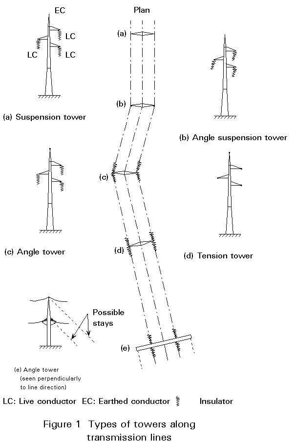
The towers support one or more overhead lines serving the energy distribution. Most frequently three-phase AC circuits are used requiring three live conductors each. To provide safety against lightning, earthed conductors are placed at the top of the tower, see Figures 1 and 2.
The live conductors are supported by insulators, the length of which increases with increasing voltage of the circuit. To prevent short circuit between live and earthed parts, including the surrounding environment, minimum mutual clearances are prescribed.
Mechanically speaking, the conductors behave like wires whose sag between their points of support depends on the temperature and the wire tension, the latter coming from the external loads and the pre-tensioning of the conductor. As explained in Section 2.4, the size of the tension forces in the conductor has a great effect upon the tower design.
An overhead transmission line connects two nodes of the power supply grid. The route of the line has as few changes in direction as possible. Depending on their position in the line various types of towers occur such as (a) suspension towers, (b) angle suspension towers, (c) angle towers, (d) tension towers and, (e) terminal towers, see Figure 1. Tension towers serve as rigid points able to prevent progressive collapse of the entire line. They may be designed to serve also as angle towers.
To the above-mentioned types should be added special towers required at the branching of two or more lines.
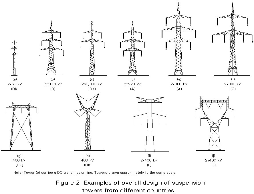
In Figure 2 examples of suspension tower designs from four European countries are presented. Note similarities and mutual differences.
Before starting the design of a particular tower, a number of basic specifications are established. They are:
a. voltage.
b. number of circuits.
c. type of conductors.
d. type of insulators.
e. possible future addition of new circuits.
f. tracing of transmission line.
g. selection of tower sites.
h. selection of rigid points.
i. selection of conductor configuration.
j. selection of height for each tower.
The tower designer should notice that the specifications reflect a number of choices. However, the designer is rarely in a position to bring about desirable changes in these specifications. Therefore, functional requirements are understood here as the electrical requirements which guide the tower design after establishment of the basic specifications.
The tower designer should be familiar with the main features of the different types of insulators. In Figure 3 three types of insulators are shown. They are all hinged at the tower crossarm or bridge.
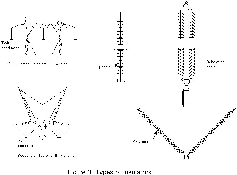
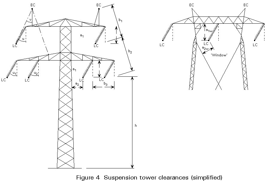
Figure 4 shows the clearances guiding the shape of a typical suspension tower. The clearances and angles, which naturally vary with the voltage, are embodied in national regulations. Safety against lightning is provided by prescribing a maximum value of the angle v. The maximum swing u of the insulators occurs at maximum load on the conductor.
The loads acting on a transmission tower are:
a. dead load of tower.
b. dead load from conductors and other equipment.
c. load from ice, rime or wet snow on conductors and equipment.
d. ice load, etc. on the tower itself
e. erection and maintenance loads.
f. wind load on tower.
g. wind load on conductors and equipment.
h. loads from conductor tensile forces.
i. damage forces.
j. earthquake forces.
It is essential to realize that the major part of the load arises from the conductors, and that the conductors behave like chains able to resist only tensile forces. Consequently, the dead load from the conductors is calculated by using the so-called weight span, which may be considerably different from the wind span used in connection with the wind load calculation, see Figure 5.
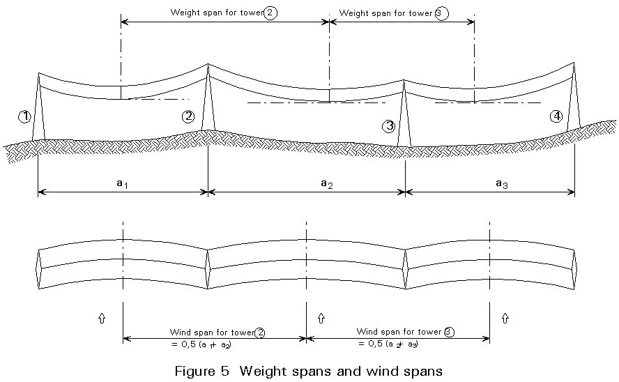
The average span length is usually chosen between 300 and 450 metres.
The occurrence of ice, etc. adds to the weight of the parts covered and it increases their area exposed to the wind. Underestimation of these circumstances has frequently led to damage and collapse. It is, therefore, very important to choose the design data carefully. The size and distribution of the ice load depends on the climate and the local conditions. The ice load is often taken as a uniformly distributed load on all spans. It is, however, evident that different load intensities are likely to occur in neighbouring spans. Such load differences produce longitudinal forces acting on the towers, i.e. acting in the line direction.
The wind force is usually assumed to be acting horizontally. However, depending on local conditions, a sloping direction may have to be considered. Also, different wind directions (in the horizontal plane) must be taken into account for the conductors as well as for the tower itself. The maximum wind velocity does not occur simultaneously along the entire span and reduction coefficients are, therefore, introduced in the calculation of the load transferred to the towers.
The tensile forces in the conductors act on the two faces of the tower in the line direction(s). If they are balanced no longitudinal force acts on a tower suspending a straight line. For angle towers they result in forces in the angle bisector plane, and for terminal towers they cause heavy longitudinal forces. As the tensile forces vary with the external loads, as previously mentioned, even suspension towers on a straight line are affected by longitudinal forces. For all types of towers the risk of mechanical failure of one or more of the conductors has to be considered.
The loads and loading cases to be considered in the design are usually laid down in national regulations.
The outline of the tower is influenced by the user's functional requirements. However, basically the same requirements may be met by quite different designs. In general, the tower structure consists of three parts: the crossarms and/or bridges, the peaks, and the tower body.
Statically speaking, the towers usually behave like cantilevers or frames, in some cases with supplementary stays. For transmission lines with 100 kV voltage or more, the use of steel lattice structures is nearly always found advantageous because they are:
By far the most common structure is a four-legged tower body cantilevering from the foundation, see Figure 6. The advantages of this design are:
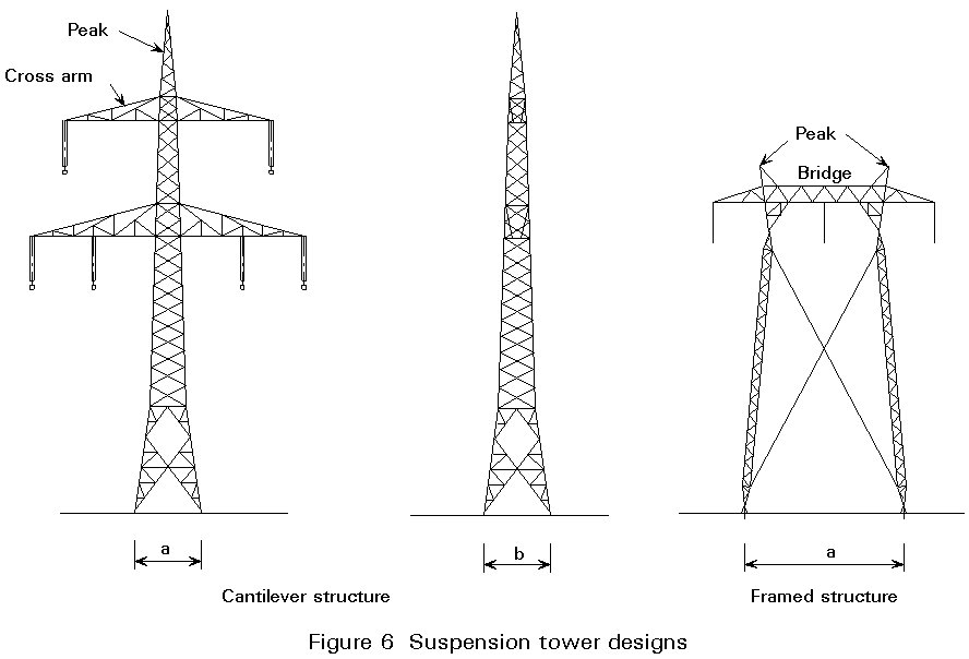
The following remarks in this section relate mainly to a cantilever structure. However, many features also apply to other tower designs.
For a cantilever structure, the tower legs are usually given a taper in both main directions enabling the designer to choose the same structural section on a considerable part of the tower height. The taper is also advantageous with regard to the bracing, as it reduces the design forces (except for torsional loads).
The bracing of the tower faces is chosen either as a single lattice, a cross bracing or a K-bracing, possibly with redundant members reducing the buckling length of the leg members, for example see Figure 6. The choice of bracing depends on the size of the load and the member lengths. The most common type is cross bracing. Its main advantage is that the buckling length of the brace member in compression is influenced positively by the brace member in tension, even with regard to deflection perpendicular to the tower face.
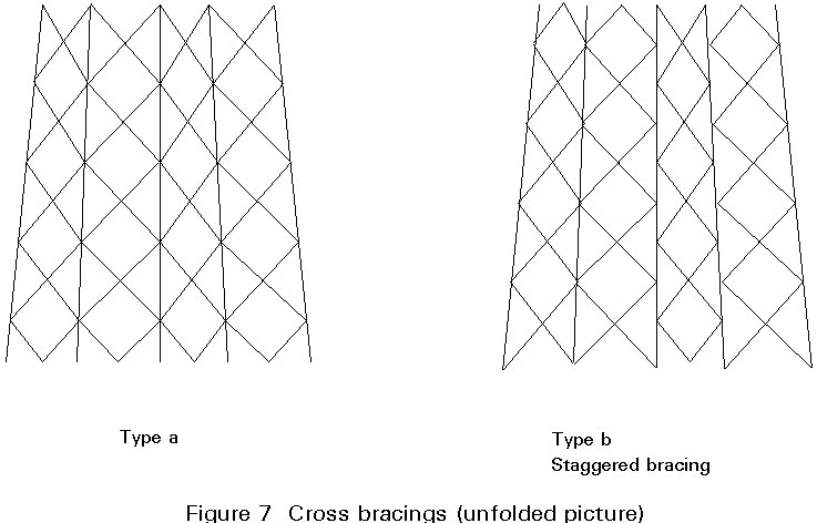
Generally, the same type of bracing is chosen for all four tower body faces, most frequently with a staggered arrangement of the nodes, see Figure 7. This arrangement provides better space for the connections, and it may offer considerable advantage with respect to the buckling load of the leg members. This advantage applies especially to angle sections when used as shown in Figures 10 and 11, since it diminishes the buckling length for buckling about the 'weak' axis v-v. For further study on this matter see [1].
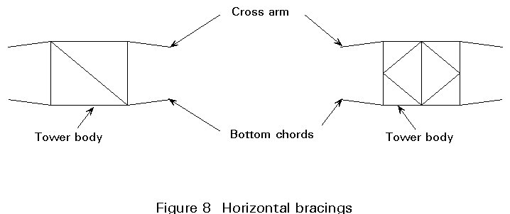
Irrespective of the type of bracing, the tower is generally equipped with horizontal members at levels where leg taper changes. For staggered bracings these members are necessary to 'turn' the leg forces. Torsional forces, mostly acting at crossarm bottom levels, are distributed to the tower faces by means of horizontal bracings, see Figure 8.
Cross arms and earthwire peaks are, in principle, designed like the tower itself. However, as the load on the cross arms rarely has an upward component, cross arms are sometimes designed with two bottom chords and one upper chord and/or with single lattice bracings in the non-horizontal faces.
Generally, the structural analysis is carried out on the basis of a few very rough assumptions:
These assumptions do not reflect the real behaviour of the total system, i.e. towers and conductors, particularly well. However, they provide a basis from simple calculations which have broadly led to satisfactory results.
Generally speaking, a tower is a space structure. It is frequently modelled as a set of plane lattice structures, which are identical with the tower body planes together with the planes of the cross arms and the horizontal bracings mentioned in Section 2.5.
In a simplified calculation a four-legged cantilevered structure is often assumed to take the loads as follows:
a. centrally acting, vertical loads are equally distributed between the four legs.
b. bending moments in one of the main directions produce an equal compression in the two legs of one side, and equal tension in the two legs of the other side. The shear forces are resisted by the horizontal component of the leg forces and the brace forces (thus, the leg taper has a significant influence on the design of the bracing).
c. torsional moments broadly produce shear forces in the tower body faces, i.e. in the braces.
A classical analysis assuming hinges in all nodes leads to very simple calculations. However, the effect of redundancies should be considered, especially concerning the forces and moments in the brace members.
Although this approach is satisfactory in most cases attention must be drawn to the function of redundant members, which in some cases may change the load distribution considerably. In addition, the effect of fixed connections (as opposed to hinged connections) must be considered, since they produce moments in the bracing members. The effect of eccentricities in the joints should also be taken into account, see Section 2.7.
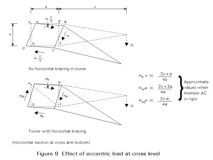
Finally, the distribution of an eccentric horizontal load is studied. In Figure 9 the force H is acting at the cross arm bottom level. Without horizontal bracing in the tower, three tower body planes are affected by H. The deflections of the plane lattice structures of the tower body deform the rectangle ABCD to a parallelogram A¢ B¢ C¢ D¢ . By adding member AC or BD this deformation is restricted and all four tower body planes participate in resisting the force H.
The detailed design is governed by a number of factors influencing the structural costs once the overall design has been chosen, such as:
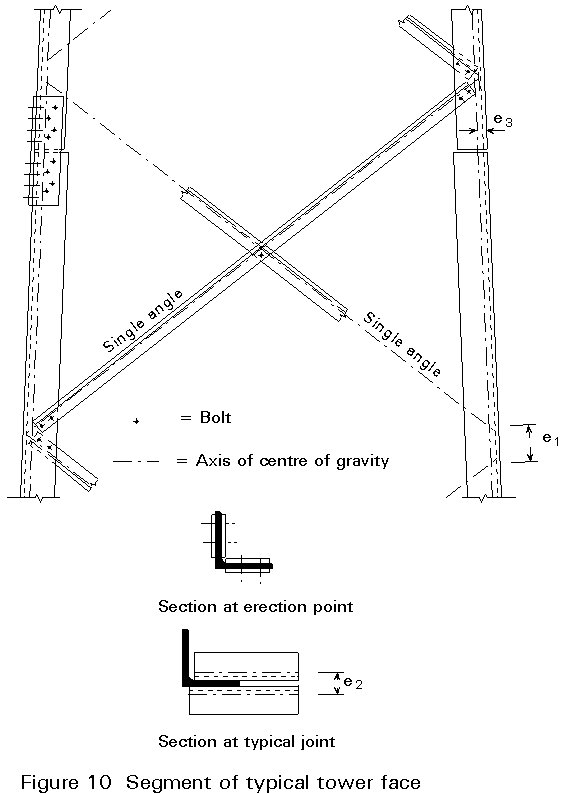
As an introductory example of design and calculation, a segment of a four-legged tower body is discussed, see Figure 10. All members are made of angle sections with equal legs. The connections are all bolted without the use of gussets, except for a spacer plate at the cross bracing interconnection. This very simple design requiring a minimum of manufacturing work is attained by the choice and orientation of the leg and brace member sections.
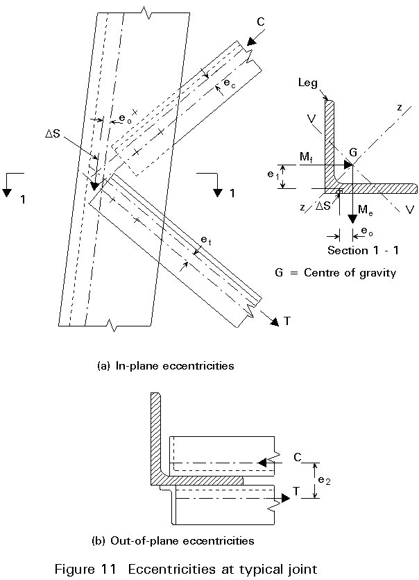
By choosing the design described above, some structural eccentricities have to be accepted. They arise from the fact that the axes of gravity of the truss members do not intersect at the theoretical nodes. According to the bending caused by the eccentricities they may be classified as in-plane or out-of-plane eccentricities. In Figure 11, the brace forces C and T meet at a distance eo from the axis of gravity. The resultant force DS produces two bending moments: Me = DS´ eo and Mf=DS´ e1. These moments are distributed among the members meeting at the joint according to their flexural stiffness, usually leaving the major part to the leg members. As z-z is the 'strong' axis of the leg section, a resultant moment vector along axis v-v will be advantageous. This is achieved, when eo=-e1¢ . In this case C and T intersect approximately at the middle of the leg of the section. Usually this situation is not fully practicable without adding a gusset plate to the joint.
Additional eccentricity problems occur when the bolts are not placed on the axis of gravity, especially when only one bolt is used in the connection (eccentricities ec and et).
The out-of-plane eccentricity causing a torsional moment, V = H´ e2, acting on the leg may be measured between the axes of gravity for the brace members (see Figure 11). However, the torsional stiffness of the leg member may be so moderate - depending on its support conditions - that V cannot be transferred by the leg and, consequently, e2 must diminish. The latter causes bending out-of-plane in the brace members.
The leg joint shown in Figure 10 is a splice joint in which an eccentricity e3 may occur. In this case there is a change of leg section, or the gravity axis for the four (or two) splice plates in common does not coincide with the axis of the leg(s). For legs in compression the joint must be designed with some flexural rigidity to prevent unwanted action as a hinge.
The joint eccentricities have to be carefully considered in the design. As the lower part of the leg usually is somewhat oversized at the joint - this is, in fact, the reason for changing leg section at the joint - a suitable model would be to consider the upper part of the leg centrally loaded and thus, let the lower part resist the eccentricity moment. The splice plates and the bolt connections must then be designed in accordance with this model.
The bolted connections might easily be replaced by welded connections with no major changes of the design. However, except for small structures, bolted connections are generally preferred, as they offer the opportunity to assemble the structural parts without damaging the corrosion protection, see Section 2.8.
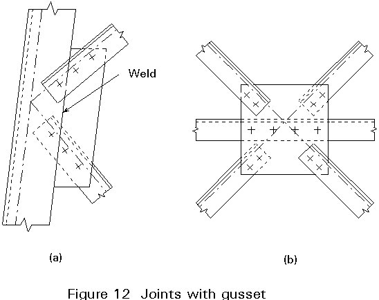
This introductory example is very typical of the design with angle sections. Nevertheless some additional comments should be added concerning the use of gussets and multiple angle sections.
The use of gussets is shown in Figure 12. They provide better space for the bolts, which may eliminate the in-plane eccentricities, and they allow for the use of double angle sections. In the latter case out-of-plane eccentricities almost vanish.
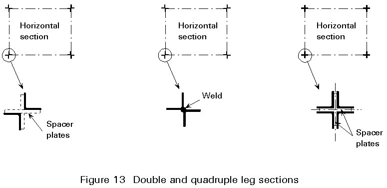
For heavily loaded towers it might be suitable to choose double or even quadruple angle sections for the legs. Figure 13 shows some possibilities.
Towers designed with other profiles than angles
In principle any of the commercially available sections could be used. However, they have to compete with the angle sections as regards the variety of sections available and the ease of designing and manufacturing simple connections. So far only flat bars, round bars and tubes have been used, mostly with welded connections. The use is limited to small size towers for the corrosion reasons mentioned above.
In other contexts, e.g. high rise TV towers, circular sections may be more interesting because their better shape reduces wind action.
Construction joints and erection joints
The tower structure usually has to be subdivided into smaller sections for the sake of corrosion protection, transportation and erection. Thus a number of joints which are easy to assemble on the tower site, have to be arranged. Two main problems have to be solved: the position and the detailing of the joints.
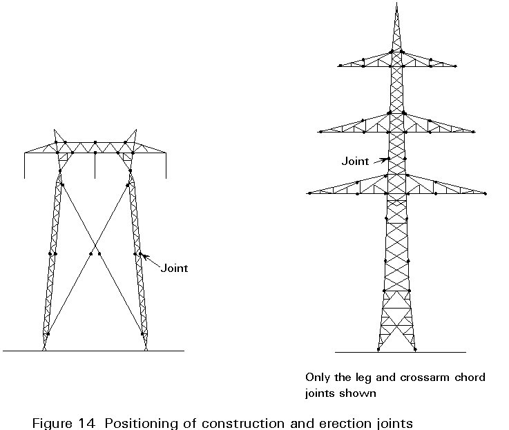
In Figure 14 two examples of the joint positions are shown. The framed structure is divided into lattice structure bodies, each of which may be fully welded, and stays. The cantilevered structure usually is subdivided into single leg and web members.
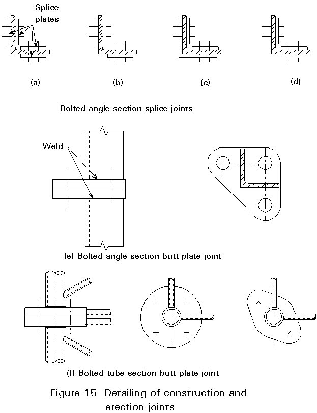
The two types of joints are lap (or splice) joints and butt plate joints. The former is very suitable for angle sections. The latter is used for all sections, but is mostly used for joints in round tube or bar sections. Figure 15 shows some examples of the two types.
Today, corrosion protection of steel lattice towers is almost synonymous with hot-galvanising, possibly with an additional coating. The process involves dipping the structural components into a galvanic bath to apply a zinc layer, usually about 100 m m thick.
No welding should be performed after galvanizing, as it damages the protection. The maximum size of parts to be galvanized is limited by the size of the available galvanic bath.
[1] European Convention for Constructional Steelwork, ECCS, "Recommendations for Angles in Lattice Transmission Towers", ECCS Technical Committee 8, Brussels 1985.
Recommendations concerning slenderness ratios and buckling curves from leg and web members taking into account redundancies and eccentricities.
Comprehensive treatment of all aspects on high-voltage transmission lines, i.e. planning, conductors, insulators and other equipment, design and calculation of towers, foundation, corrosion protection and erection.
Recommendations for establishing design criteria and loadings.
Definition of wind action.