
ESDEP WG 15B
STRUCTURAL SYSTEMS: BRIDGES
To identify the principal actions on bridge structures and to describe how they are considered in design.
None.
Lecture 1B.2.1: Design Philosophies
Lecture 1B.2.2: Limit State Design Philosophy and Partial Safety Factors
Lecture 1B.3: Background to Loadings
All other Lectures 15B.
This lecture begins by explaining the reasons why actions on bridge structures are considered with considerable precision. It identifies the principal actions for highway and railway bridges. It discusses the means by which considerations of individual actions are combined to ensure that an economic design of adequate reliability is achieved.
It is customary to devote considerably greater attention to the assessment of loads for bridges than for many other types of structure. There are several reasons for this greater precision:
In the future the Eurocode for the Basis of Design and Actions on Structures [1], will identify the loads and other actions which need to be considered in bridge design, and define their characteristic values. Parts 2 of Eurocode 3 [2] and Eurocode 4 [3] will provide detailed guidance for the design of bridges and plated structures. The combinations of actions which need to be considered, will be defined in these documents and appropriate partial safety factors will be presented [4].
None of these documents will be available for some time. This lecture is written in general terms. Representative examples of practice in defining actions on bridges are provided to illustrate general principles and also to provide indications of orders of magnitude.
Dead load on bridges includes the weight of structural materials (self-weight) and also the so-called superimposed dead load (surfacing, finishes, etc.), Figure 1.
The weight of the surfacing generally has a large variation during the life of a bridge and so particular care must be taken to assess its design value. It is customary to adopt a conservative estimate of initial thickness to determine the characteristic loading and then to apply a high partial factor.
Traffic loads on bridge decks are used to simulate the effects of vehicles and/or pedestrian loads. Some traffic loads represent the weight of real vehicles that can travel over the bridges; other values and distributions are chosen in such a way that they produce maximum internal forces in bridge structures similar to the ones produced by real vehicles.
Four types of loads are specified in the European national codes:
Figure 2 shows the combination of knife-edge load and uniformly distributed load on a 3-span structure which gives the greatest value of mid-span moment.

Impact effects (dynamic effects) of traffic loads are in general specified in the codes. For highway bridges an enhancement of up to 25% of the static load is often used to take impact into account.
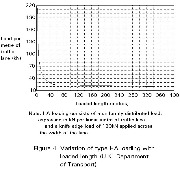
a) Uniform distributed load (Figure 3).

This load simulates the effects of normal permitted vehicles. In some national codes its value is constant and independent of the loaded area. In other codes the load value decreases with the area occupied by the load, see for example Figure 4. Distributed load is applied on the traffic lanes and over the lengths that give the extreme values of the stress resultant (or internal force) being considered. It may be continuous or discontinuous.
b) Knife edge load
This load (Figure 5) is usually associated with the uniform distributed load. It does not represent a single axle load, but is a device to ensure that, together with the uniform distributed load, the vertical shear and the longitudinal moments that may occur in real bridge elements are produced.

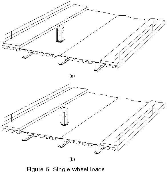
c) Single wheel load
Some national codes specify the application of a single heavy wheel load placed anywhere on the carriageway, with a circular or rectangular contact area (Figure 6).
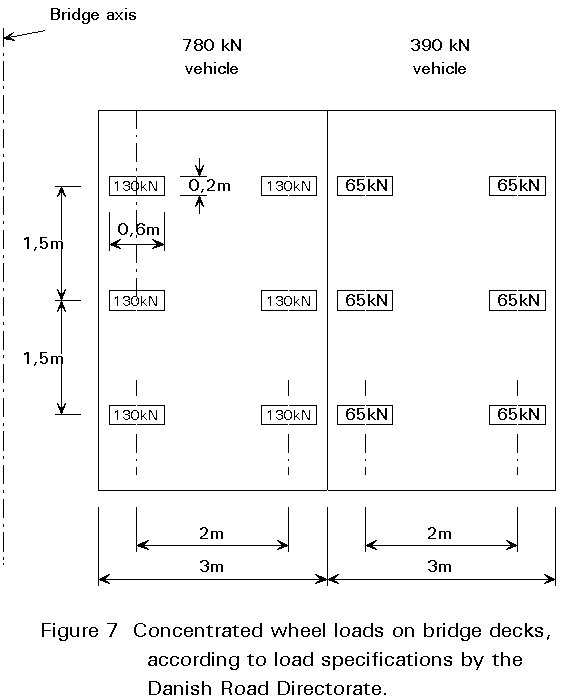
d) Truck load
This load is intended to represent the extreme effects of a single heavy vehicle. In some countries it consists of a specified number of wheel loads and arrangements, Figure 7. Other codes indicate only the distances between axles, the spacing of wheels in each axle, and the minimum number of axles.
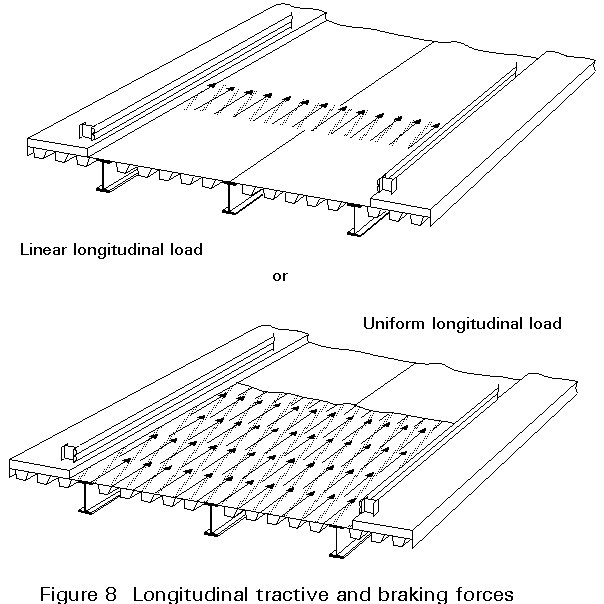
These forces (Figure 8) result from the traction or braking of vehicles and they are applied to the road surface, parallel to the traffic lanes.
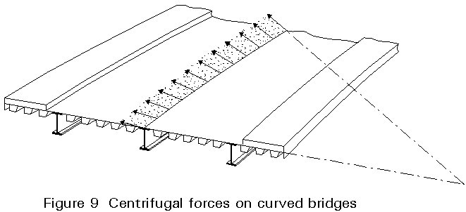
Curved bridges are subject to centrifugal forces applied by the vehicles that travel on them. These forces are related to the traffic loads by a coefficient, a, whose value depends on the radius of the curve, R, and on the design speed, v by:
a
= CV2/rwhere
C is a constant
Some codes consider a uniform distributed radial load and others divide it into concentrated loads, Figure 9.
Many highway bridges, in urban and non-urban areas, have sidewalks (footpaths) for pedestrian traffic and/or cycle tracks. On these areas a uniform distributed load is usually considered, Figure 10. Some codes indicate also that one wheel load applied on the sidewalks should be considered.

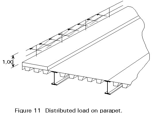
Parapets of footpaths and cycle tracks that are protected from highway traffic by an effective barrier are designed to resist horizontal distributed force applied at a height of 1m above the footway. The nominal value of this force is about 1,5kN/m, Figure 11.
When footways and cycle tracks are not separated from the highway traffic by an effective barrier, design loads have to recognise the need to contain traffic in the case of an accident. These loads are considerably higher and include an alternative concentrated load.
Superimposed dead loads on railway bridges usually include the rails, the sleepers, the ballast (or any other mean for transmission of train loads to the structural elements), and the drainage system, Figure 12.

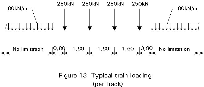
Typical train loads on bridges consist of a number of concentrated loads preceded and followed by a uniformly distributed load. Both loads are equally divided between the two rails, Figure 13.
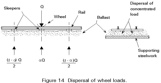
Some national codes specify the criteria to be used for the distribution of concentrated loads by the adjacent sleepers and the dispersal through the ballast onto the supporting structure, Figure 14.
Train loads specified in the codes are equivalent static loadings and should be multiplied by appropriate dynamic factors to allow for impact, oscillation and other dynamic effects including those caused by track and wheel irregularities.
Values of dynamic factors depend on the type of deck (with ballast or open-deck) and on the vertical stiffness of the member being analyzed. For open-deck bridges values of dynamic factors are higher than for those with ballasted decks.
Consideration of the vertical stiffness is made by adopting formulae in which the dynamic factor is a function of the length, L, of the influence line for deflection of the element under consideration. Some codes use different formulae for impact factors associated with bending moment and vertical shear.
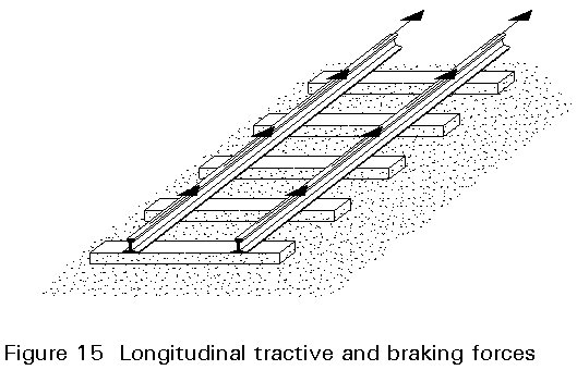
These forces, which are a percentage of train loads, are considered as acting at rail level in a direction parallel to the tracks, Figure 15.
The nominal centrifugal load is applied corresponding to with the train loads and acts radially at a height of 1,8m above rail level. Its value is obtained by multiplying the train loads by a coefficient, a = cv2/r (as in 2.4) which is proportional to the square of the greatest speed, v, envisaged on the curve and increases with the inverse of the radius, r, of curvature.
A single nominal load, acting horizontally in either direction at right angles to the track at the top of the rail is taken to provide for the lateral effect of the nosing of vehicles, such as locomotives, Figure 16.
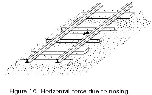
This force, usually with a value of about 100 kN, should be applied at a point in the span to produce the maximum effect in the element under consideration.
The vertical effects of the horizontal force on secondary elements such as rail bearers should be considered.
The wind actions on a bridge depend on site conditions and geometrical characteristics of the bridge. The maximum pressures are due to gusts that cause local and transient fluctuations about the mean wind pressure. Design gust pressures are derived from the design wind speed defined for a specified return period.
A reduced wind pressure can be used in erection calculations to allow for the much shorter period during which the relevant structure is at risk.
The design wind load, normally taken as horizontal, and acting at the centroids of the exposed areas is given by
![]()
or
![]()
where:
r
is the density of the air (1,226 kg/m3 under normal conditions)Vc is the design gust speed
At is the solid area in normal projected elevation
CD is the drag coefficient (defined in the codes)
![]() is the dynamic pressure
is the dynamic pressure
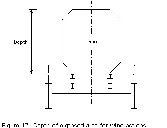
The area At should include the exposed area of the traffic where appropriate. Drag coefficients should be considered accordingly.
Exposed area of traffic on bridges has the length corresponding to the maximum effects and in general a height of 2,50m above the carriageway in highway bridges and 3,70m above rail level in railway bridges, (Figure 17).
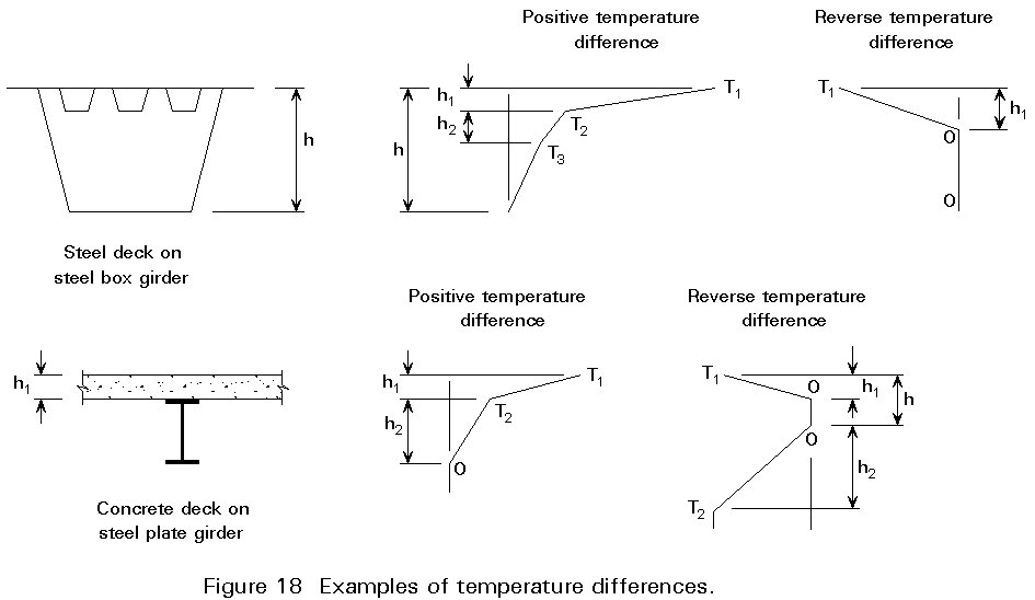
Daily and seasonal fluctuations in air temperature cause two types of thermal actions on bridge structures, as referred in the codes:
a) Changes in the overall temperature of the bridge (uniform thermal actions)
b) Differences in temperature (differential thermal actions) through the depth of the superstructure, Figure 18.
The coefficient of thermal expansion for steel structures may be taken as 12 x 10-6 °C
These two types of thermal effect produce different types of response in a bridge. The overall change in temperature causes overall changes in bridge dimensions in an unrestrained structure (or so-called thermal stresses if these potential changes in dimension are resisted by the supports). Usually the structure is allowed to expand with minimal restraint by the provision of expansion joints and sliding bearings.
The non-linear temperature distribution in Figure 18 lead to self-equilibrating stresses on all cross-sections, even in an unrestrained structure. One way to understand these stresses is to consider the structure initially to be fully restrained and subjected to these non-linear temperatures, as shown in Figure 19(i). It is then progressively released to give the final stress distribution of Figure 19(i) d). It is noteworthy that the releases have led to both axial strain and curvature.
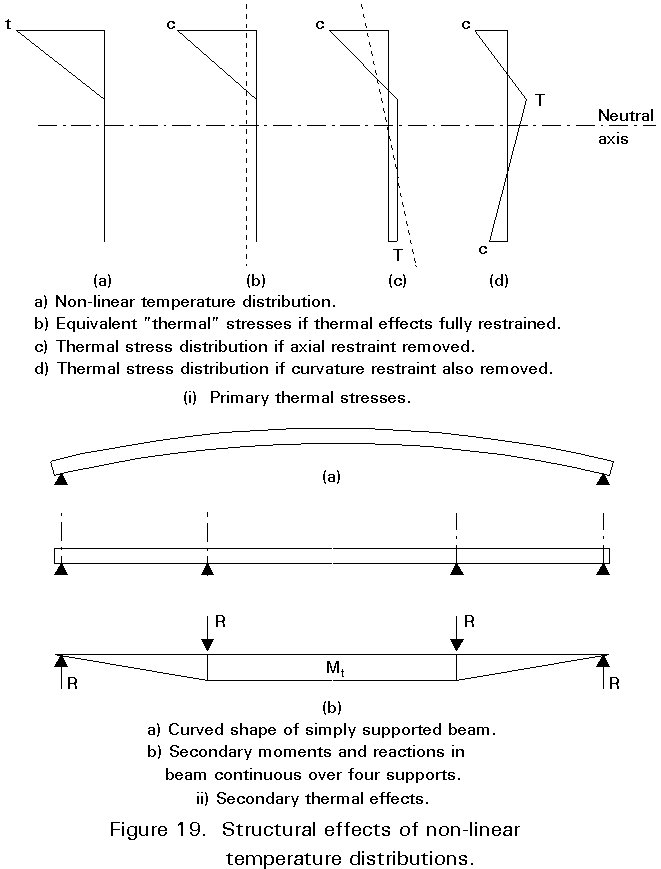
If the structure is simply supported on sliding bearings, it is free to expand and curve as shown in Figure 19(i)c). However, a continuous bridge will not be able to curve freely and will develop secondary "thermal" moments, Mt, and reactions shown in Figure 19(ii)b).
In composite girders the effect of concrete shrinkage should be considered.
In principle the shrinkage gives a stress independent of the strain in the concrete. It is therefore equivalent to the effect of a differential temperature between concrete and steel.
Generally, shrinkage effects are only taken into account when the effect is additive to the other action effects.
The settlements of foundations determined by geotechnical calculations should be taken into account during design of the superstructure.
For continuous beams the decisive settlements are differential vertical settlements and rotations about an axis parallel to the bridge axis.
For earth anchored bridges (arch bridges, frame bridges and suspension bridges) horizontal settlements have to be considered.
Where larger settlements are to be expected it may be necessary to design the bearings so that adjustments can be made, e.g. by lifting the bridge superstructure on jacks and inserting shims. In such a case the calculations should indicate when adjustments have to be made.
In European countries located in seismic areas, i.e. in southern Europe, earthquake actions should be considered in bridge design.
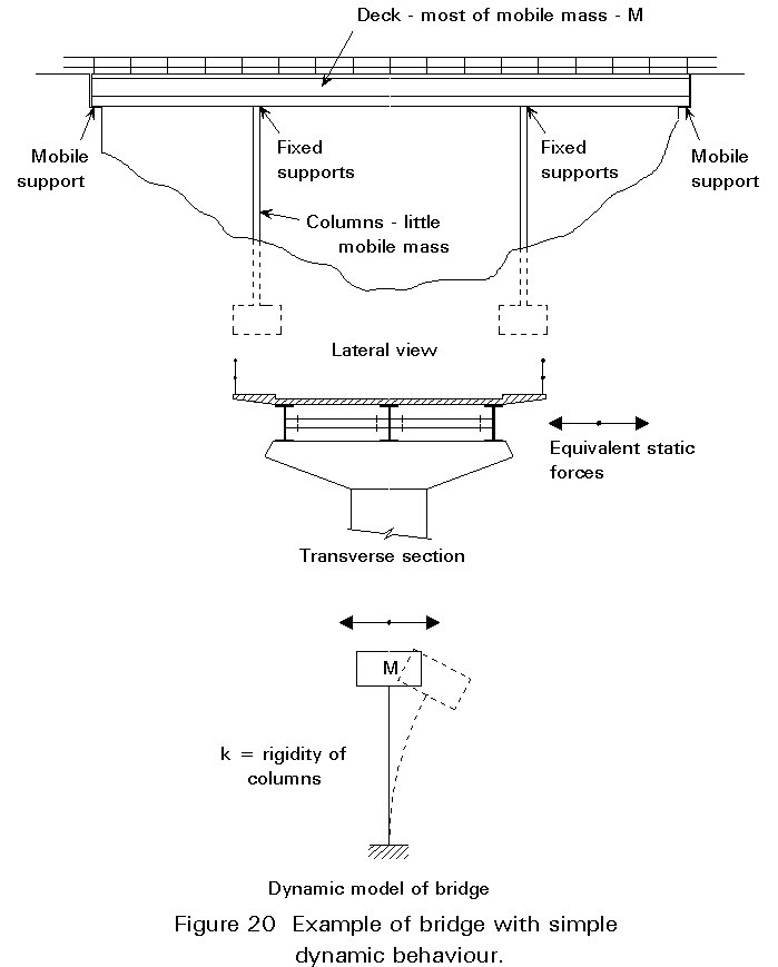
The behaviour of a structure during an earthquake depends on its dynamic behaviour, namely its natural vibration modes and frequencies, and damping coefficients.
When the bridge has a simple dynamic behaviour, for instance when the first vibration frequency is much lower than the other ones, the seismic action may be reduced to an equivalent static force, see Figure 20.
All piers and other portions of the bridge should be designed to resist the forces induced by flowing water, floating ice or drift.
In structures where essential load-carrying elements may be subject to impact by vehicles, ships or aircraft, the consequences should be considered as accidental load cases - unless the risk of such collisions is evaluated as being so small that it can be neglected.
It is necessary in many cases to allow partial destruction or damage of the element which is directly hit. This element then has to be repaired after the collision. It should, however, be shown that the partial destruction of a single element will not lead to a total collapse of the entire structure.
To reduce the consequences of collisions it may be necessary to limit the movements of movable bearings so that only the movements due to temperature effects can take place without restraint.
It should be checked whether the unavoidable friction in bearings can induce forces or moments that have to be considered in the design of the structural elements.
Modern sliding bearings are characterized by a coefficient of friction of approximately 0,03 if the sliding surfaces are absolutely clean. However, to take into consideration some deterioration in the sliding surfaces as well as tolerances in the positioning of the bearings it is recommended that the design is based on a typical coefficient of friction of 0,05.
In a continuous beam with a fixed bearing at the centre and longitudinally movable bearings on either side, expansion (or contraction) of the beam induces symmetrical frictional forces. These forces are in horizontal equilibrium if a constant coefficient of friction is assumed, and they normally result in moderate axial forces in the main girders. However, to take into account the uncertainty in the magnitude of frictional forces it may be reasonable to assume full friction in the bearings on one side of the fixed bearing and half friction on the other side.
Erection loads are especially important for the design of composite and long-span bridges.
In long-span bridges the internal forces existing when the construction is completed are frequently adjusted by movements of supports or, in the case of cable stay bridges and suspension bridges, by adjustment of the cable forces.
In composite bridges the formwork for the deck is usually supported by the steelwork alone, and is not removed until after the deck becomes composite. The stresses induced in the composite deck by the removal of the formwork may be small enough to neglect, but in principle, they are a form of permanent prestressing, which can be considered in load combinations.
Limit state design is probabilistic and load factors are determined to ensure that the probability of exceedence of a particular set of design actions (i.e. characteristic actions times partial safety factors) is satisfactorily small. The probability of two different actions, e.g. limiting live load and limiting wind load, occurring simultaneously is clearly less than that for either individual occurrence. It is therefore desirable to achieve the same reliability for different combinations of actions by adopting different partial safety factors on the individual components. Table 1 below shows the different factors that are used in the UK for two different combinations of action (load). Combination 1 is dead load plus live load. Combination 2 is dead load plus wind load plus live load.
|
Load |
gfL At ultimate limit state combination |
|
|
1 |
2 |
|
|
Dead Superimposed Dead Wind with Dead + S.Dead with Dead + S.Dead + Live Vertical Live Load HA alone HA with HB or HB alone |
1,05 1,75
1,50 1,30 |
1,05 1,75
1,40 1,10
1,25 1,10 |
Table 1 Combination of Actions (Loads)
(Source: BS 5400: Part 2)
For simple bridges which are constructed from Class 1 or Class 2 sections, it is not necessary to consider the detailed build-up of stresses in the bridge as it is constructed. Such structures have sufficient ductility to redistribute stresses within the cross-section. It is therefore only necessary to check the adequacy of the structure at each stage in construction and to ensure that the completed structure can carry both fixed and variable actions, i.e.dead plus live loads.
Larger structures are usually constructed of Class 3 or 4 sections and it is not safe to assume that redistribution of construction stresses can occur. It is therefore necessary to model in some detail the build up of construction stresses throughout the construction process. Figure 21 shows the sequence for a typical three-span composite highway bridge. Each case is analyzed elastically and the stresses are summed at critical cross-sections.

Experience and computational effort are required to determine the critical variable action effects for all relevant cross-sections in the bridge.
The analysis has to determine governing values of the following global effects:
In addition it is necessary to determine governing values of load moments, shears and torsions on the concrete slab or orthotropic deck.
National practice for this analysis varies considerably - at least partly in response to variations in national load specifications. However, it is possible to identify some general trends.
[1] Eurocode 1: "Basis or Design of Actions on Structures", CEN (in preparation).
[2] Eurocode 3: "Design of Steel Structures" Part. 2: Bridges and Plated Structures, CEN (in preparation).
[3] Eurocode 4: "Design of Composite Steel and Concrete Structures" Part. 2: Bridges, CEN (in preparation).
[4] Sanpaolesi, L., Sedlacek, G., Merzenich, G.M. "The Development of European Codes and Supporting Standard for the Design of Bridges,". ECCS 2nd International Symposium on Steel Bridges, Paris, April 1992.