ESDEP WG 5
COMPUTER AIDED DESIGN
AND MANUFACTURE
To discuss possible future developments in data transfer between different stages in the steel construction process, through a product model approach. To indicate the benefits that might be realised as a result of this and how such changes can be achieved.
Lecture 5.1: Introduction to Computer Aided Design and Manufacture
None.
The processes of exchanging information at various stages of a steel construction project are reviewed briefly. The potential advantages of enabling this transfer to be made directly between computers rather than, as at present, on paper are outlined. The basic requirements that must be met before such a system can be implemented are discussed in principle, and the practical ways in which it might be achieved are considered. The role of the management information system is explained, and a realistic approach to implementation throughout the industry is outlined.
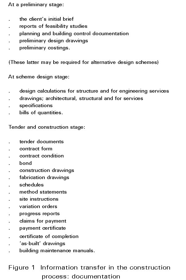
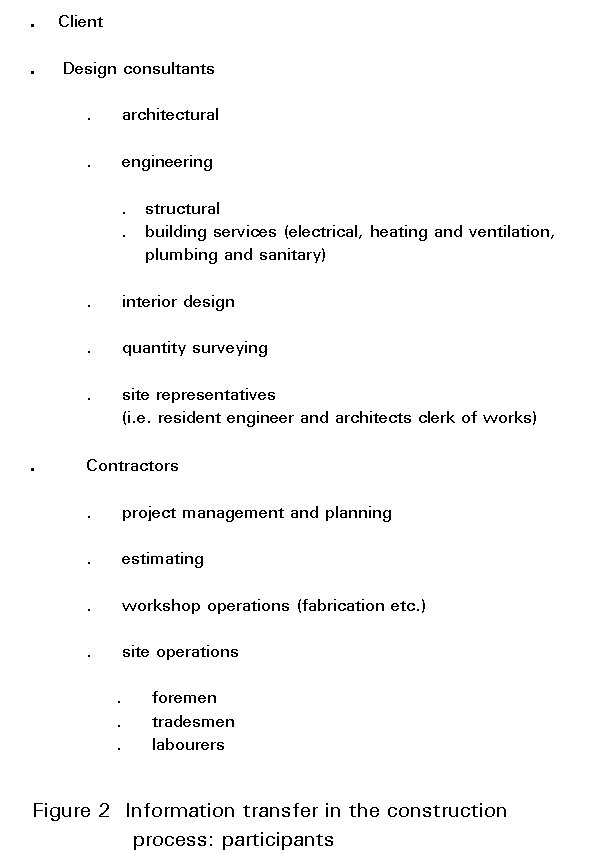
The progress of a building project from client's brief to completion of execution entails the generation and transfer of large quantities of information, much of it in the form of paper documents. Many people contribute to the project as it progresses through its various phases.
Inefficiency and disruption results from the need to translate information from one format to another - as occurs, for example, in the creation of workshop drawings for the steel fabrication - as well as from the transfer of inadequate or erroneous information, and from late changes which may entail laborious reworking.
The aim of this lecture is to extend ideas relating to information exchange standards, developed for manufacturing industry, to the processes of information transfer between the various stages of construction, in order to render these more efficient and economical.
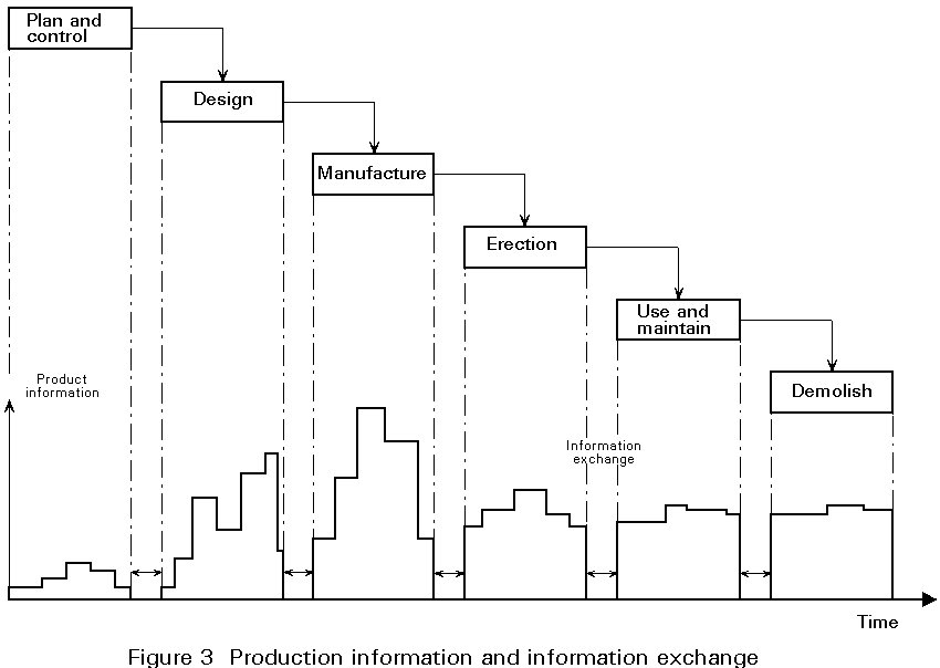
Figures 1 and 2 give an indication of the information generated and exchanged within the construction process, and the various parties which may need to be involved in such exchanges of information. Figure 3 represents a portion of this information schematically, using the terminology of the Product Model - the product being in this case the steelwork aspect of the building project. This figure marks the stages in the life of the product, and illustrates the accumulation of product data as product life progresses. Information exchanged between phases often has particular legal significance. A particular example is the set of information exchanges which take place at the end of the design phase and which are marked by the signing of a contract. There is a particular onus on the participants to ensure the completeness, correctness, clarity and finality of such information exchanges, as errors can waste time and money and variations lead to contractual claims.
Common sense would suggest that the quantity of information exchange should be confined to the essential - consistent, of course, with the conveyance of an adequate understanding of requirements.
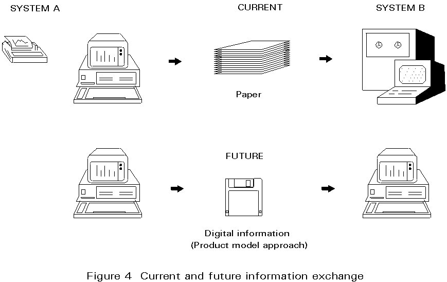
At present this information is exchanged between participants as hard copy, i.e. as reports, calculations, drawings, etc. Interpreting this data at each stage of information exchanged can be a time consuming process, particularly if there are ambiguities, or if some aspects are incomplete. Modifications in the information generally result in changes within all subsequent stages of the product model route. Changes in the client brief, for instance, cause reworking of design calculations, drawings, details, etc. and if made late in the programme can result in significant delays. Substitution of alternative section sizes at the detailing stage to take account of material availability, for example, may have less consequence, but even so the required changes to details may be time consuming. It is always a danger too that isolated changes have implications for other aspects of construction which are not identified in the rush to make the corrections. Something as simple as a change in beam depth, for instance, may have considerable significance for the accommodation of services.
The present system does, however, provide useful opportunities for checking information since at each stage of information transfer the data is examined afresh. It also allows for considerable flexibility in the system, with some information being passed on in a partially complete form, and in a variety of formats. Feedback between later stages in the product model route and those earlier in the process are also relatively straightforward.
More use is being made of computers within each stage of the product model route, with a view to increasing efficiency. One of the most time consuming aspects of using computers is entering data, and significant savings can therefore be achieved if the effort required for data input is minimised. This can be achieved by transferring data between successive stages in the product model route electronically rather than as hard copy.
Future information exchange will therefore involve wider use of computers to reduce manual input of data and provide a better flow of information relating to the steelwork 'product'. For instance information derived from design calculations could be transferred directly to a computer-aided design (CAD) system to avoid duplicating definitions of basic data such as beam spans, column heights, etc. and to enable the output from the calculations (section sizes, beam reactions, etc.) to be taken directly into the next stage.
Some developments have already taken place in this sense. The integration of general arrangement drafting and detailing systems, and the output of 3-D modelling systems leading directly into numerically controlled machines for fabrication. This means replacing the present limited conventions and protocols for information exchange, both manual and computer based, with a more rigorous unified information exchange system which can apply across the entire construction industry, and which is capable of operation in all phases of the project's life.
Such a system requires:
i. the establishment of a unified computer based product description.
This requires data in a sufficiently comprehensive form to describe all relevant aspects of the product at all stages.
ii. the creation of standards for the transfer of information between different computer systems and organisations.
iii. the creation of information management systems - to control information changes, access rights and quality assurance.
These requirements can be illustrated by the following simple examples:
i. A computer program for the elastic analysis of frames requires member cross-sections to be described in such terms as area and moment of inertia. It does not require a description of how the area is distributed throughout the section, i.e. what its shape is. Such a description would, however, be inadequate to generate connection details. It is, therefore, desirable to have a single format which would accommodate both needs, permitting an efficient transition from analysis to drafting.
This is a somewhat trivial example. Most frame analysis programmes now allow definition of cross-sections by reference to a standard library. However it does illustrate the point that data which is sufficient to describe the product at one particular stage in the process may be inadequate for other stages.
ii. Working on a range of products, a steelwork fabricator has to produce shop drawings from engineering design information originating from a variety of software and hardware systems, some of which are mutually incompatible. It would seem advantageous if this fabrication could access directly the graphical information base created by the designer in each case. This would necessitate a CAD system capable of information exchange with all others on the market. CAD developers have tended to concentrate on transfer of information between computers running the same software, i.e. theirs, rather than facilitating exchange of information with machines running software produced by a competing CAD developer. An information exchange format which is particular to a CAD package is termed the 'native' data exchange format of that system.
Considerable progress has been made in this direction with regard to alphanumeric data. The ASCII format provides a basic standard so that text produced using one wordprocessor system, for instance, can be output in this form enabling it to be read directly by other systems or application programs. Dealing with text is a relatively simple matter because it involves a limited number of unique characters. Even so, the ASCII standard provides for the basic characters only with no formatting signals to indicate different text styles, subscripting, etc. Data for presenting information graphically is even more complicated, but some standards have been established, IGES and DXF files serve a similar function, providing a standard of data appropriate to drawing instructions, enabling the output from the CAD system to be interpreted by another. However it should be clear that this is not in itself sufficient to provide a full description of what is being drawn. The full product model description requires much more complete information.
An essential first step towards an integrated approach is the development of a standard specification for the organisation of technical information on structural steelwork. This specification is referred to as the 'logical product model' and provides a standard basis for the production of interfaces between structural steelwork software products. When the technical information on a particular structural steelwork contract is arranged according to the 'logical product model' specification, it is then simply referred to as a product model. The product model approach can be used to transfer information between all sorts of software products by using product model files (computer files) to transfer the information automatically. Consistent versions of existing paper documents can then be generated, as required, from this unified digital description, or product model.
In broad terms, the system would work in the following way:
Figure 4 compares the traditional approach with the product model approach for information exchange. The main advantages of the product model approach are that it will offer flexibility for users to configure and develop systems from the software products they prefer (provided each product they wish to use has a product model interface).
A product model for steelwork construction is currently being developed within the Eureka EU130 CIMSTEEL project.
In the long term, the approach is capable of being developed to achieve full database integration of software products. It is the target system architecture activity which aims to map out the future part of development.
The native exchange file formats are 'de facto' standards established by particular software vendors and remain under their control. In contrast, the concept of a neutral file format implies a universal standard independent of any particular vendor. Such standards originate typically from research projects but are now increasingly coming under the control of international standards bodies.
One of the principal goals of current research projects, e.g. EUREKA, ESPRIT, is to make it possible to transfer information easily and inexpensively between the many different software products already available or being developed for the structural steelwork industry. This implies direct digital transfer of information obviating the need for manual interpretation of drawings, etc.
Examples of software products involved are:
The main benefits of linking software are that time and effort can be saved, and transcription errors can be eliminated.
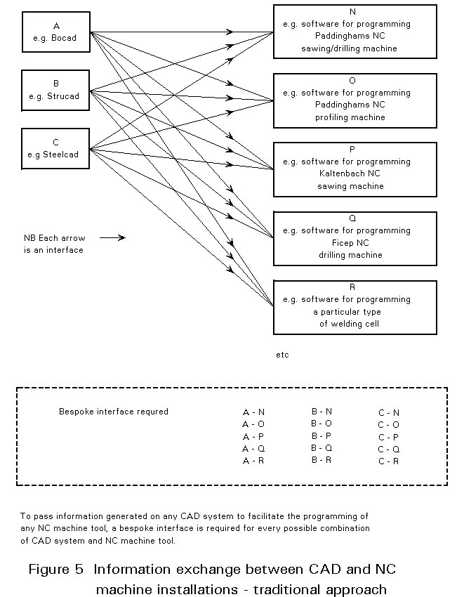
Traditionally, wherever a company requires an efficient means of information exchange between specific software products, a new piece of purpose-written software, 'an interface', has to be produced. Unfortunately, an interface will only work with the particular pieces of software for which it was specifically written in the first place. Thus, every time a new software product is introduced, new interfaces have to be produced to link with each and every other piece of software with which it needs to exchange information. The simple interface of two pieces of software solves only a local problem and creates a localised increase in efficiency (Figure 5). To achieve a solution to meet the requirement of the whole industry a wider perspective is required.
The IGES Standard
The most widely supported of the current generation of neutral exchange file formats is the Initial Graphical Exchange Standard (IGES). It originated in 1980 with the then United States National Bureau of Standards. By 1988 Version 4.0 had been published, and at the time of writing this lecture, a final version - to be Version 5.0 - is awaited. While IGES has extended its ability to represent information and addressed problems of efficiency, the standard has grown increasingly complex. It is similar in principle to the DXF system, which is a proprietary product of Autodesk.
The neutral file concept established by IGES led to the evolution of several other data exchange standards, each targeted on the needs of a specific group of CAD/CAM users. In each case, the objective was to make the exchange process more efficient and reliable, and to maximise the ability of the developed data exchange file format to represent particular classes of engineering information.
While considerable technical progress was made by these various standards projects, the result was a proliferation of data-exchange formats. It was recognised that the solution lay in a single second-generation neutral file standard which would provide a unified framework for data exchange by all sectors of engineering. The result was the new emerging International Standards Organisation (ISO) STEP Standard.
The ISO STEP Standard
STEP, the Standard for the Exchange of Product model data seeks to provide consistent data models across a broad range of engineering applications which would be applicable to the whole life-cycle of engineering products. Thus the STEP data models will (eventually) enable all aspects of a construction project to be represented, from conception through to the structure's ultimate demolition.
So in some respects, STEP is just another neutral data exchange file format. However, the true significance of STEP is that it uses much definitive second-generation engineering data exchange standards based on the concept of a product model. It is interesting to note that during the early development of IGES it was 'Product Data' that was to be exchanged. The switch to 'Product Model' in STEP reflects a recognition that it is information (i.e. meaning), not data, that has to be transferred (see Figure 6).

Currently, STEP is little more than a powerful enabling technology and, while it may be a long-term task to compile the necessary component product models, the technology for the implementation of STEP will soon be available [1, 2].
To make real progress in the area of the future management information systems it is necessary to have a clear and common view of how it relates to the product model. The main point to recognise is that the product model is limited to technical information. Management information must be dealt with separately by the MIS.
Figure 7 presents a simplistic view of the structural steelwork design and manufacture process with boxes representing the functions of scheme design, detail design, fabrication and erection. Types of software products which may be used are shown under each function. At the top of the diagram is the Management Information System, which monitors and controls the functions. At the bottom of the diagram is the Product Model which provides the technical information needed by the software products in the form of product model files.

Although a clear division between technical and management information can be defined theoretically, in reality the MIS will need to:
Thus, in addition to a 'management information controller' the MIS should also include a 'product model information controller' whose function will be to manage the flow of product model information in the form of product model files. Figure 8 illustrates the way in which this could be arranged. In essence, the MIS controls both the management functions and the transfer of product model information. Product model files are stored in the product model file store and are used to transfer technical information to enable the various pieces of technical software to perform their required operations for any particular contract going through the factory.

It should be noted that Figure 8 represents product model file interfacing, and does not include database integration of products model information. As such, it can only represent a step towards the development of fully integrated systems.
Incremental Implementation
It has to be fully recognised that many of these long term aims have only a theoretical meaning today. As a result practical incremental implementation is essential so that the industry can start to reap the benefits in the shorter term. The shorter term goals of common information exchange standards allow the interfacing of systems enabling the industry to take the first vital steps towards implementation of computer integrated manufacture (CIM).
Recognising the different ways in which steelwork companies are managed, and will continue to be managed, it is evident that an all encompassing standard for management information is going to be very difficult to achieve.
However, if the finance, sales and marketing, personnel, and administration functions are excluded for the time being, then a common approach is feasible for:
It is in these areas that an industry-wide approach could be developed. An industry MIS could be produced covering these functions which would comprise a number of modules operating in conjunction with a management information database and a product model file store.
[1] National Economic Development Council (NEDC), Information Transfer in Building, NEDO, London, 1990.
[2] Watson, A. S., CAD Data Exchange, Proc. Institution of Civil Engineers, Part 1, 1990, Vol. 88, December, 955-969.