ESDEP WG 1B
STEEL CONSTRUCTION:
INTRODUCTION TO DESIGN
To outline the developments in the design of iron and steel for structures.
Lecture 1B.4.1: Historical Development of Iron and Steel in Structures
Lectures on the metallurgy of steel; a useful background to many other lectures, notably those dealing with the design of particular structural types.
Structural theory as known today owes most of the intellectuals of France while in the late 18th Century and the early part of the 19th, Britain took the lead in practical design and application. 18th Century empiricism was replaced first by large-scale proof-loading and tentative calculation, followed after 1850 by component testing allied to elastic analysis with testing soon relegated to quality control. In the late 19th Century, the powerhouse of engineering thought shifted gradually to France, Germany and America. Elasticity and graphical analysis held sway for about 100 years until they were challenged by plastic theory and the computer, with automation replacing hand work in production and erection.
The developments in materials, theory and technique were all related but varied from country to country due to different needs, shortages and opportunities. This lecture outlines the developments in design methods for structural steelwork, illustrating this with a number of examples of iron and steel structures.
Up to the late 18th Century, structures were designed essentially on the basis of proportion. To some extent, this meant no more than deciding whether sizes looked right - that is, familiar - but in many, perhaps almost all periods, there were some rules or statements by authorities which were almost as firm as our codes of practice today. The difference is that they were not based on strength or stress but on shape and scale. Stress, in the sense that the word is used in engineering today, did not exist. The materials were essentially masonry and timber with a little iron.
With masonry the real problem has almost always been one of stability rather than crushing of the material and, until quite recently, stability was usually established visually. Early tie-bars of iron in masonry construction were, it seems, also sized by eye.
With timber in the 18th and early 19th Centuries, deflection was the main problem. If it was stiff enough, it must be strong enough. This may seem illogical to us today but with timber, which tends to indicate its distress by creaking, sagging and even splitting long before failure, stiffness was not a bad criterion for adequacy. Nevertheless, timber floors did sometimes collapse, perhaps most often due to ill-conceived joints.
Until the early 19th Century it is far from clear who fixed the sizes of timbers or the connections in trusses. Probably, it was the carpenters working on experience, observation and possibly copy books of details. In spite of growing knowledge of the strength and stiffness of different materials, this unscientific approach sufficed for the majority of construction until well into the 19th Century - at least in Britain, but perhaps less so in other parts of Europe.
In the early 19th Century, intuition gave way to calculation for all materials and theory took over to an ever increasing extent. However, the aim of this lecture is not to outline the development of structural theories for which most credit must go to the intellectuals of France, but to show how, in Britain particularly but also elsewhere, these theories were gradually incorporated in the work of ordinary engineering designers.
The fact that some of the theories were incorrect was of no importance provided that these were related to tests and that like was being compared with like. For instance, having established that for a rectangular beam the bending strength was proportional to:
(bd2) x (a constant depending on the material)
where b and d are breadth and depth of section, respectively, it did not matter whether you used Galileo's or Mariotte's incorrect theories of the 17th Century or Parent's elastically correct one of the 18th, provided that the constant was derived from bending tests and used in comparable circumstances for the assessment of the bending strength of other cross-sections. In 1803, Charles Bage developed a perfectly valid method of designing cast iron beams on the basis of tests and Galileo's bending theory.
Among the earliest mathematical design handbooks in Britain, if not actually the first, were Peter Barlow's book on timber, originally issued in 1817, and Thomas Tredgold's books on timber and cast iron, first issued in 1820 and 1822, respectively. Both Barlow and Tredgold made acknowledgements to earlier work by Girard and others on the Continent. It is worth looking quickly at the methods advocated in these books to get some idea of how at least a British engineer could have tackled the problems of fixing the sizes of structural members in the 1820s. The extent to which these handbooks were actually used is uncertain.
Much of the present practice with steel derived originally from timber which makes a good starting point.
In the simple case of direct tension, Barlow used the word 'cohesion' which is 'proportional to the number of fibres or to the area of section'. He tabulated 'cohesion on a square inch', as did Tredgold, both basing their values on their own experiments or those by Musschenbroek, Emerson, Rondolet and others. Thus, for direct force, the concept of stress was there in all but the name.
For timber, Barlow stated in relation to 'absolute strength' that 'practical men assert that not more than one fourth of this ought to be employed' but implied that so large a reduction was not necessary. Neither the effect of knots and other defects nor the concept of an overall factor of safety to cover all variables seemed to come into his thinking. Tredgold merely accepted a factor of safety of 4 on the ultimate strength of timber as disclosed by tests.
With timber, there was little need to consider beams of anything other than rectangular section. Barlow and Tredgold gave practical rules both for strength and deflection. For instance, for a rectangular beam of length L with a load of W, Tredgold's rule for strength amounted to:
W = ![]()
where the constant C allowed for the strength of the material, the loading conditions and different units for length and cross-section. There was no reference to bending moments or section moduli. All was direct, the tabulated values of C being derived from tests on small sections of comparable timber loaded in the same way.
It is notable that both Barlow and Tredgold devoted as much space to deflection as to strength, a clear follow-on from the time when sagging was the first and, perhaps the only, indication of inadequacy.
Tredgold suggested 1 in 480 as a reasonable limit for deflection in relation to span.
When considering floor joists, Tredgold's emphasis on deflection was particularly strong. He gave a rule, again controlled by a mysterious constant, which rightly relates the span, spacing and breadth of the joists to the cube (not the square) of their depth but, curiously, is independent of the load. He explained that the constant was based on scantlings 'found to be sufficiently strong' whereas 'it is difficult to calculate the weight that a floor has to support'. Thus, in this field anyway, the dominance of strength rather than proportion was not yet complete.
For cast iron, Tredgold, who certainly produced the first real calculator's guide to the material, moved closer to modern thinking than in his book on timber, but in some respects went very wrong, although pardonably so.
Again, he advocated a deflection limit of 1 in 480 for beams but also what we would call a safe working stress (f) of the frighteningly high value of 106 N/mm2 (6,8 tonf/in2). This value he considered to be the elastic limit in bending (based on tests on 25 x 25mm bars of cast iron). He also found the 'absolute strength of cast iron bars to resist a cross-strain' (modulus of rupture) of these small bars to be 280-400 N/mm2 and thus thought he had what amounted to a factor of safety of 2,6 to 3,8.
He then assumed, or so it seems because he said very little directly about it, that using the same working stress (f) in direct tension he would have a similar margin of safety as in bending. He assumed further and with more justification that using this stress (f) again in compression, the safety margin would be at least as high. Thus all one needed to do was to design to the elastic limit as a working stress and all would be well.
In the case of direct tension, Tredgold discounted the testing techniques which had given ultimate tensile strengths of around 110-120 N/mm2 and had no reason to know that later bending tests on larger beam castings were to show a modulus of rupture of as low as 110 N/mm2 for comparable iron. The last of these errors was specially understandable because the variation in the modulus of rupture with size of casting has still not been fully explained. Nevertheless, his thinking led to a potentially dangerous set of assumptions. He even suggested cast iron links at his universal working stress of 106 N/mm2 as more robust than wrought iron ones for suspension bridges.
It must not be implied that Tredgold got it all wrong. His method of calculating deflection appears to be generally correct. Further, with cast iron, there was a demand for cross-sections other than rectangular and Tredgold went into the properties of these sections at some length, getting the right answer with the symmetrical ones, but possibly not for quite the right reason, and going only slightly astray on the position of the neutral axis with T-sections and similar shapes.
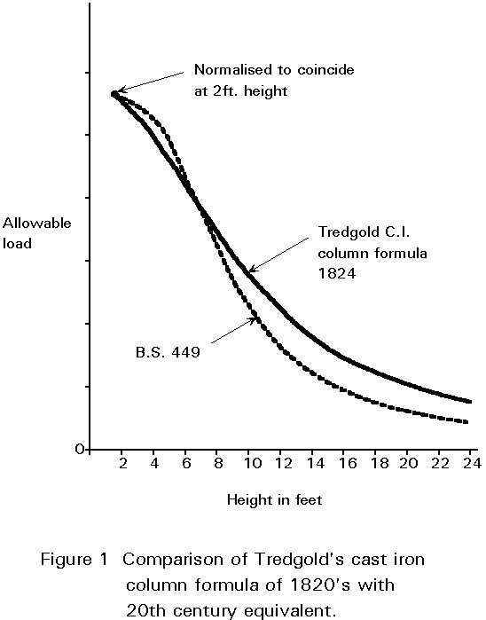
On cast iron columns, as on timber ones, Tredgold's recommendations were basically sound. He was certainly aware of the problem of buckling and Timoshenko gives him credit for being the first to introduce a formula for calculating safe stresses for columns (see comparison in Figure 1). However, for ties he got into a tangle once more on the effect of length. He thought long ties to be stronger than short ones, visualising them as being subject to something like buckling in reverse which increased their strength with length.
The sad point about Tredgold's safe working stress, apart from his curious error on direct tension which had only a limited effect, is that if it had been applied to wrought iron it would have been almost universally sound. Also it would have been well ahead of any other practical guidance of the time, at least in Britain. The detailed thinking behind some of Tredgold's methods is not always easy to understand today, and it is doubtful whether many of his contemporary readers succeeded or even tried to follow this in detail. It is even more doubtful how many engineers in Britain read or understood the writings of men like Thomas Young or John Robinson or the works of the vast galaxy of theorists in other parts of Europe. Some certainly tried and the level of success would be hard to measure today.
Tredgold's book on cast iron was translated into French and German and ran into five editions, with the same errors perpetuated, the last being issued in 1860. However, from the 1830s onwards his practical advice was challenged by Eaton Hodgkinson's advocacy of his 'ideal section' for cast iron beams and his simple formula related to this.
Eaton Hodgkinson showed by direct loading tests that cast iron was about six times as strong in compression as in tension and proportioned his beam accordingly. His simple formula (Figure 2) has been repeated in engineering handbooks until well into this century.
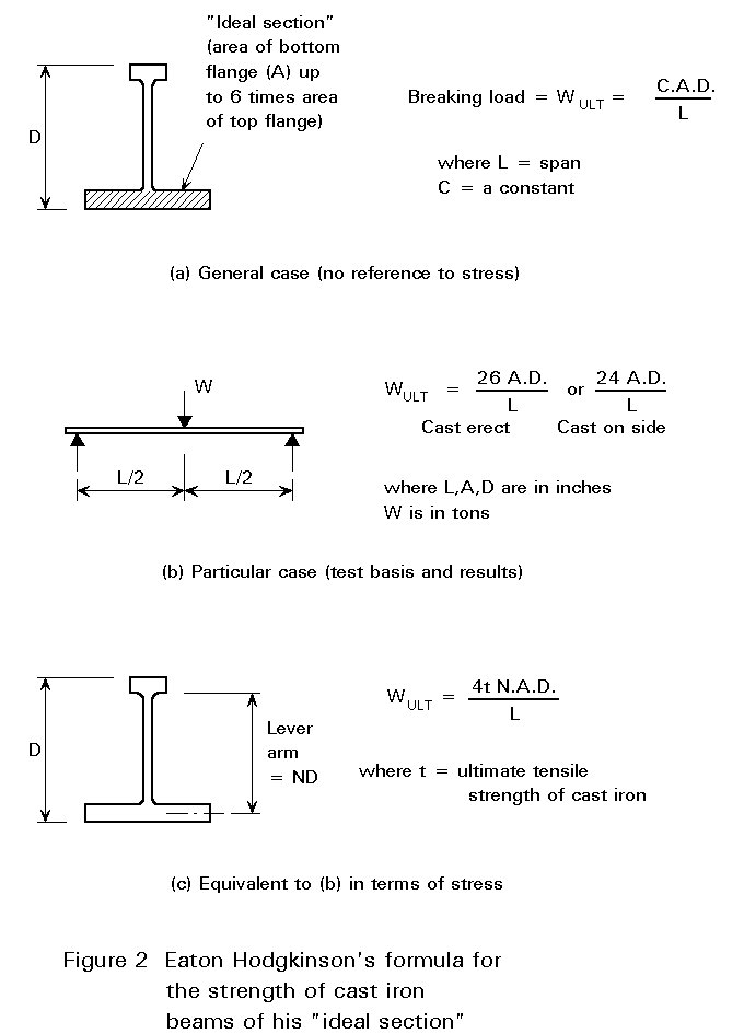
All was derived from bending tests and would be equivalent to saying:
Ultimate resistance moment = N.D.A.t
where t is the ultimate tensile strength of cast iron. If N = say 0,9, the value of t derived from his formula would be 6,7 to 7,2 tonf/in2 which is a very plausible range. The significant point is that even Eaton Hodgkinson was not thinking in terms of stress but of a constant relating tests under one set of conditions to practical use in the same form. Eaton Hodgkinson also made extensive tests on cast iron columns and published the results with practical advice in 1840. This advice formed the basis for further recommendations for many decades.
Until towards the middle of the 19th Century, wrought iron was used almost exclusively in tension for such applications as chains, straps, tie rods and boiler plates.
The tensile strength of wrought iron was fairly well understood throughout Europe from early in the 19th Century, the mean value being about 400 N/mm2. Thus, even allowing for quite wide variations, its tensile strength could be relied upon to be about three or four times that of cast iron and with an incomparably greater ductility.
It was the behaviour of wrought iron in bending which eluded engineers until towards the middle of the 19th Century. There were, of course, the French wrought iron flooring units associated with Ango and St. Fart but these units were really tied arches.
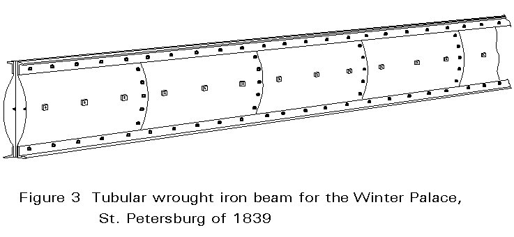
Discounting the seemingly empirical wrought iron beams of 1839 (Figure 3) used in the Winter Palace at St Petersburgh which had no wider influence, the wrought iron beam dates from the mid 1840s when small rolled I beams were produced both in Britain and France. However, the really important breakthrough came from the research and testing for the Britannia and Conway tubular bridges. This work was a major achievement which, more than any other event, established the technique of building up structural sections of all sizes from rolled angles and plates by riveting. It made riveted wrought iron the premier structural material for almost 50 years. It also marked the climax of an era of component testing and proof-loading and heralded its end.
Whatever may have been written about the strength of materials, engineers in this period tended to feel happier with tests than theory when facing new or uncertain conditions.
Proof-loading was widely applied to cast iron beams, in many cases all beams being individually tested. Records of important buildings indicate that the modulus of rupture under test often approached Tredgold's high figure of 106N/mm2. However unwise this figure may have been if the beams passed with a central point load, with the usual distributed loadings they must have had a factor of safety of 2 against the proof load.
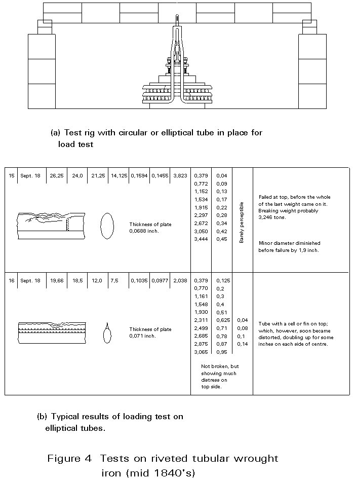
Not only were full-size components such as beams and columns tested, but also small sections of different materials to establish their properties. Further, the development of new forms depended almost entirely on tests. Effectively the tubes for the Menai and Conway bridges were designed by experiment (Figure 4). Starting from the concept that wrought iron was just a less brittle form of cast iron, initial calculations were based on Eaton Hodgkinson's formula for cast iron beams. Tests then showed that unlike cast iron, wrought iron was apparently weaker in compression than in tension. Further tests proved that this was not a property of the material but due to plate buckling, a phenomenon not found in cast iron beams because of their heavy section. Other tests proved that for tubular beams, a rectangular shape was more efficient structurally than a circular or elliptical one, provided that its top and sides were stiff enough.
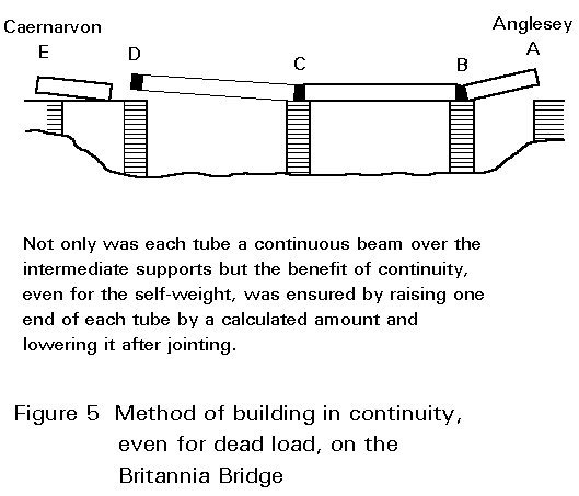
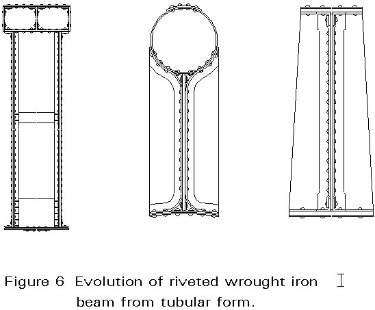
The tubes were designed for continuity over the intermediate supports even for self-weight (Figure 5) but it is not clear whether the continuity analysis in Edwin Clark's book of 1850 was used in the design or in retrospect. Here again, modelling and testing probably paid a large part in the decision making. Irrespective of how the thinking may have developed, it led to the seemingly perfect form of a continuous tube with cellular top and bottom flanges, web stiffeners on its sides and trains running through the middle. At this stage, the form of web and flange stiffening seems to have been arrived at empirically. The tubular form of compression member gradually evolved into the simple I beam of today. Figure 6 shows some steps in this transition. It would, perhaps, be unfair to speculate on the amount of iron which might have been saved if the sides of the tubes had been open and triangulated. Such trusses could not then have been analysed, but nor, when work started, could riveted wrought iron box or I beams.
There is no space here to go into all the advances in understanding which accrued from the two year development programme for this seemingly impossible structure nor to try to disentangle the disputed contributions of Stephenson, Fairbairn and Eaton Hodgkinson. The more one looks at this stupendous achievement, the clearer it becomes that it was the testing which came first and showed 'how' and the theory which followed up and explained 'why'. Engineers in Britain throughout the 19th Century were frightened of mathematics.
It is notable that in this same book with the analysis of continuity, Edwin Clark still felt constrained to say of 'transverse strain':
"The complete theory of a beam, in the present state of mechanical science, is involved in difficulties. The comparative amount of strain at the centre of the beam where the strain is greatest, or at any other section, is easily achieved but the exact nature of the resistance of any given material almost defies mathematical investigation".
Because of the magnitude of the achievement, we may be overestimating the understanding of those responsible. Certainly the dispute over the Torksey Bridge in 1850 showed that continuity was not widely understood.
This may be the point where a short diversion on terminology is appropriate. In the first half of the 19th Century the word 'stress' virtually did not exist in engineering. What is referred to as stress today was called strain or sometimes, if tensile, cohesion, but 'strain' also seems to have been used to denote a force (e.g. a strain of 10 tons). There was some uncertainty in the use of these terms.
The relationship which really meant something was the proportional one between member size and load. If, in Tredgold's words, "the strain in lbs. a square inch which any material would bear was x then four square inches would bear 4x". That was alright for direct tension and compression but with bending, the explanations are less clear.
According to Timoshenko the concept of 'stress on an infinitesimal plane' was due to Augustin Cauchy and published in 1822. Cauchy also developed the valuable concept of principal stress but again, according to Timoshenko, it was St. Venant who first defined stress in its final form in 1845. Both Todhunter and Pearson, Timoshenko and others give W.J.M. Rankine the credit for being the first to provide rigorous definitions of stress, strain, working stress, proof strength, factor of safety and other phrases which are now commonplace in engineering.
While there is a danger of over-elevating the Menai Bridge designers today, there is an even greater risk of assuming that their new-found understanding was immediately absorbed by all other engineers. It was not, but there was a very great change in attitude mainly in the years between 1850 and 1870. This was the period when ordinary engineers learnt to calculate the sufficiency of most simple structural forms, beams in particular, and to believe in their calculations - even for major structures - without testing.
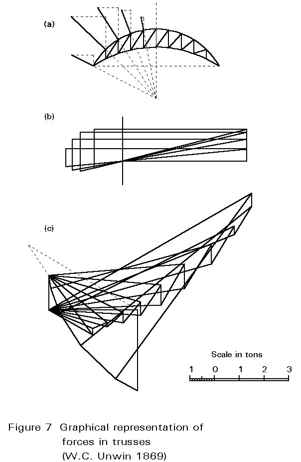
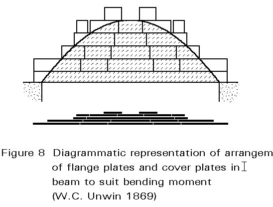
1850-1870 was also the period when it became possible to analyse the forces in trusses with certainty. Several researchers contributed to the understanding of the forces in complex but determinate trusses. Practical textbooks were published in different countries and translated into other languages, all telling roughly the same story. Rankine's "Manual of Civil Engineering" (1859) was very widely read and frequently reprinted. W.C. Unwin's "Wrought Iron Bridges and Roofs" of 1869 showed how graphical statics now dominated truss analysis (Figure 7). Unwin and others also showed how to build up flanges and cover plates to match the bending moments (Figure 8). Another interesting practical textbook is that written by Professor August Ritter of Aix-La-Chapelle Polytechnic and published in 1862. This book gives complete analyses of several notable British structures of wrought iron and was considered worth translating into English in 1878. Many of the methods of the 1850s and 1860s, although perfectly practicable, proved tedious until R.H. Bow introduced his famous notation in 1873. This was exactly the sort of systematic and almost foolproof graphical method to appeal to engineers. It has retained its popularity through many generations and has been superseded only recently for speed by the computer.
In spite of growing confidence, load testing took some time to die. Large scale tests were still being used around 1850-60 although possibly as much to satisfy clients as to reassure designers. In the late 1840s three of the crescent trusses of 47m span for the first Lime Street Station in Liverpool were erected as a unit in Turner's works in Dublin and tested first for a uniform load of almost 2kN/m2 and then for eccentric loading. These trusses have a record span and the need for assurance was understandable.
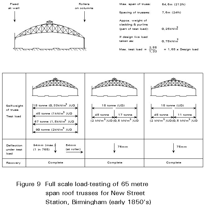
The proving of the 65m trusses for New Street Station in Birmingham (another record span completed in 1854) was even more elaborate, as show in Figure 9. Apart from testing the performance of a complete section of the roof, each tie member was proved to 139 N/mm2 before incorporation.
After about 1860, confidence in wrought iron had grown enough for testing even of major building structures to be played down, although bridge testing continued.
Provision was made for testing in the contract for St Pancras Station (completed 1868) but it was never used. The Albert Hall roof (1867-71) was erected in Fairbairn's works in Manchester to make sure it fitted together but was not load-tested. These are just examples. One could cite others to illustrate the change from intuition and physical verification to the calculation of sizes with confidence.
One reason for this change was, of course, the displacement of cast by wrought iron. Wrought iron was now recognised as a reliable material and, with rivets of definable strength it could be built up into structures virtually limitless in scale in spite of restrictions on the sizes of plate and angle which could be rolled. Further, and most important of all, by 1850 or soon after, it had become a calculable material, not just for ties and struts but also for beams.
While it was mainly the triumvirate of Stephenson, Fairbairn and Hodgkinson who established the riveted wrought iron beam, it was the 'elasticians' of the mid-century like Rankine who translated this knowledge into practical advice and showed engineers how to design with it.
With increased understanding of structural behaviour, there was a swing at this time from intuitive feelings that strength and stiffness could be increased by redundancy to simplification of forms so that they would be more amenable to precise calculation and thus to more economical sizing.
The reality of the known behaviour of wrought iron was limited to the range of stress within which the theorists were thinking. With a working stress generally not exceeding 77 N/mm2 (the Board of Trade figure in Britain) there is no doubt that wrought iron behaved elastically and that the theory of elasticity, which became the gospel for engineers in the third-quarter of the 19th Century, was wholly relevant.
Hooke's law held. Young's modulus was a constant. There was no need to think about factors of safety. You had a working stress to control your design, even though you might still have been calling it a strain, and you had every reason to feel confident.
Stress, as we understand it, had not only been born but, by now, was the controlling factor in almost all structural design, at least with iron, and iron was becoming increasingly dominant where a high level of performance was needed. Elastic theory, graphical analysis and definite rivet strengths were all that the designer required for full confidence. Around 1850, Britain had such confidence and was still leading the field in iron construction, although much was being done in parallel elsewhere, in particular in France, Germany and America. As the century progressed, the initiative moved from Britain with engineers like Moisant (Chocolat Menier Factory) and Eiffel and his colleagues catching much of the limelight.
The commercial transition from wrought iron to steel roughly between 1880 and 1900, permitted higher working stresses (generally 93 N/mm2 instead of 77N/mm2) and the use of larger rolled sections. Initially, it had virtually no effect on design and detailing.
Cast iron columns continued to be used widely until about 1890-1900 but were then superseded first by wrought iron but mainly by steel. Further theoretical work on buckling went in parallel with more advanced formulae for safe loads. It seems that amongst practising engineers the question of buckling of struts and of thin plates remained the least well understood aspect of structural design throughout the 19th Century.
It is not the intention of this lecture to chart the development of theoretical knowledge but rather to show how this related to the ordinary engineer in the design office. To follow the understanding of bending, shear and instability in more detail, the works referred to in the list of Additional Reading should be consulted.
In the early part of the present century, the greatest advances both in theoretical understanding of structures and in practice were associated with the airship and aircraft industries. For bridges, buildings and other 'heavy' structures the changes were mostly associated directly or indirectly with welding.
The general introduction of welding in the 1930s (with Britain lagging behind other parts of Europe and America) radically altered techniques of fabrication and introduced the possibility of joints as stiff as the members they connected. This development in turn had its effect on design with more emphasis on 'portal framing' for buildings and stability through stiff joints rather than diagonal bracing.
The big change in design thinking came with plasticity in the late 1930s although ultimate-load thinking with the concept of the plastic hinge has taken some time to replace elastic theory. In fact, it has not wholly done so yet. Safe stresses are still quite dominant after a reign of nearly 150 years, but their use is declining.
In the future, engineers are likely to be able to achieve far greater efficiency by considering 'whole structure' behaviour including the effects of cladding and partitions especially for stiffness. This approach only becomes practicable with computers but offers attractive possibilities for the years to come. The disadvantage could be a reduction in adaptability. Also the understanding of designers needs to keep pace with the growing sophistication of the design aids at their disposal.
I Those who wish to delve deeply into the way in which structural theory as we know it today first emerged in the late 18th and early 19th Centuries, would do well to go straight to the classic authors: Coulomb, Bernouli, Euler, Navier and others.
For a more general view of structural theory and how it developed, the following books are recommended:
1. Timoshenko S P. "History of the Strength of Materials", McGraw-Hill, New York, 1953.
2. Todhunter I & Pearson K. "A History of the Theory of Elasticity and of the Strength of Materials from Galileo to the Present Time", Cambridge University Press; 3 volumes 1886-93.
3. Charlton T M. "A History of the Theory of Structures in the Nineteenth Century", Cambridge University Press 1982.
4. Mazzolani F. "Theory and Design of Steel Structures" Chapman & Hall, London.
5. Heyman J. "Coulomb's Memoir on Statics: an essay in the history of civil engineering", Cambridge University Press 1972.
II For a guide to practice with iron and later steel, there were many guides and text books published, especially after 1850.
Taken as a sequence, the following books give some idea of how this advice developed:
1. Tredgold T. "Elementary Principles of Carpentry", London: Taylor 1820.
The major British work on the structural use of timber, first published in 1820 and being reprinted as late as the 1940s. There are some details on the use of iron with timber, particularly for the lengthening and strengthening of timber beams.
2. Tredgold T. "Practical essay on the strength of cast iron and other metals", London: Taylor 1822.
Also several later editions.
3. Barlow P. "A Treatise of the Strength of Timber, Cast Iron, Malleable Iron & Other Materials", London: J Weale, 1837.
The 1837 and later editions were extensively revised and added to to take account of developments in the science of the strength of materials in the railway age.
4. Unwin W C. "Wrought Iron Bridges & Roofs", 1869.
Originally lectures to the Royal Engineer Establishment, Chatham.
5. Rankine W J M. "A Manual of Civil Engineering", London 1859, and later editions.
Rankine's manuals mark the turning point in Britain, of engineering as a science founded on theory as against an art founded on practical experience and observation. They summarise and extend earlier theoretical texts, notably on theory of structures and strength of materials, and remained standard works throughout the 19th Century.
6. Warren W H. "Engineering Construction in Iron, Steel & Timber", Longmans, London 1894.