ESDEP WG 17
SEISMIC DESIGN
To give an overview of specifications for the seismic analysis and design of special structures such as bridges and storage tanks.
Lectures 17: Seismic Design
None.
The lecture is divided in two parts. Part 1 deals with bridges; Part 2 deals with storage tanks.
The design of bridges is addressed with specific reference to Eurocode 8, Part 2 [1]. The general concepts for the analysis and safety checks of steel bridge structures are summarised and discussed. For tanks, a comprehensive literature and code review is given, covering both the dynamic behaviour and the design problems related to their seismic resistance.
Bridges have been heavily stricken during several past seismic events. In Japan significant damage was caused by Kanto, Nankai, Fukui and Niigata (1964) events. Most of these failures were due to large foundation settlements, which caused excessive relative displacements and, sometimes, rigid-body failure of bridge decks due to lack of support.
The damages caused by the S.Fernando earthquake in 1971, was more closely related to the dynamic behaviour of the bridge structures. The earthquake severely affected the Los Angeles highway system. In this case failures were often due to poor performance of deck joints and bearings.
During the Loma Prieta earthquake of 1989, one section of the S.Francisco-Oakland Bay bridge and the entire Cypress Street viaduct in Oakland collapsed. A heavy death toll and significant direct and indirect economic losses resulted in the S.Francisco Bay Area.
The Bay Bridge failure was due to large longitudinal displacements of a deck section, which exceeded the length of the beam supports causing rigid-body failure.
The Cypress Street overpass failed due to poor performance of columns. The failure was probably caused by inadequate and poorly detailed horizontal ties providing insufficient confining action and shear resistance.
The philosophy for the seismic design of bridges is similar to that adopted for the design of building structures, with the additional requirement that bridges should be serviceable after the design seismic event. These structures are considered to be essential in the post-earthquake period to allow rescue and aid teams to reach the stricken areas.
More precisely, non-collapse and serviceability (at least for emergency traffic) must be ensured for an event (design event) having an acceptably low probability of exceedance during the design life of the bridge. In addition only minor damage and no disruption of serviceability can be tolerated for seismic actions with large probability of occurrence during the design life.
The requirements may be met by means of design rules which, according to Eurocode 8: Part 2 [1], can be grouped into the following categories:
The aim of these verifications is to control the non-linear structural behaviour which, for economic reasons, has to be relied upon during strong seismic motions. The aim is met by performing the following fundamental design steps:
The input seismic action must include the following aspects:
A single component of motion can be described in terms of a response spectrum, a power spectrum, or a time history representation.
In Eurocode 8: Part 2 [1], a site dependent response spectrum is defined for a horizontal component, depending on peak ground acceleration, natural period and damping factor. The type of soil affects both the shape and the intensity of the spectrum. For the vertical component the same spectrum must be adopted, scaled by a factor of 0,7.
Alternatively a power spectrum or a set of accelerograms can be adopted, provided that they are compatible with the site dependent response spectrum.
A simplified six-component input motion, including rotational excitations is also specified depending on the horizontal response spectrum (or power spectrum) and on the ground S-wave velocity.
The spatial variability of the input motion is important for long bridges. If the length of the structure is of the same order of magnitude as the length of the relevant seismic waves, the usual hypothesis of the seismic motion being equal and simultaneous at all supports points must be removed.
Stochastic models of the spatial correlation structure of the ground motion are now available. They are based on theoretical considerations regarding the wave propagation mechanism as well as on strong-motion data recorded by dense arrays of instrumentation. These models, usually given in terms of cross spectral density functions, can be directly used, together with the single-point power spectrum, to perform a random vibration analysis. Alternatively, a set of time-histories compatible with the space-time correlation structure of the design input motion can be simulated. They are then used in step-by-step linear or non-linear dynamic analyses.
Eurocode 8: Part 2 allows a simplified modelling and a response spectrum analysis taking account of the spatial variability of ground motion [1].
According to Eurocode 8: Part 2, different methods of structural analysis can be employed depending on the deck stiffness and on the overall regularity of the bridge.
If the in-plane horizontal deck stiffness is very large compared with the flexural stiffness of the piers, a simplified static analysis based on the hypothesis of a rigid deck can be adopted.
If the deck is not very stiff, but its flexibility can be adequately modelled by means of a single deformation shape, a "fundamental mode" model, essentially based on the classical Rayleigh method, can be adopted.
In other more general cases a full dynamic analysis and modelling must be performed.
A full dynamic model must be used also for skew bridges or when the bridge cannot be regarded as regular with respect to length of spans or stiffness of piers.
A site-averaged response spectrum can be used to account, in a simplified way, for different soil conditions at the various support points.
When the full dynamic model is used, a linear or non-linear analysis can be performed. Non-linear analysis can be used, based on design spectrum compatible accelerograms, to assess ductility demands in the dissipative elements and to verify that internal forces in non-ductile elements do not exceed elastic limits.
Linear dynamic analysis can be performed by reducing the response spectrum ordinates by a factor (behaviour factor or q-factor) which takes into account non-linear behaviour. The same reduced spectrum (design spectrum) is used for the determination of the equivalent static forces to be introduced in the fundamental mode and for rigid deck simplified analyses.
Different behaviour factors (q) are specified by Eurocode 8: Part 2, depending on the expected dynamic behaviour in the non-linear range: the higher the expected ductility, the larger the values of q-factor [1]. The values range from 1 (no-ductility) for arch bridges to a value of 3,5 for high ductility bridges in which most of the energy input is dissipated by the bending deformations of the piers.
The q-factor depends on both the type of structure and on the adopted detailing.
For bridges with steel piers, provisional values for q-factors are given below:
(1) Bridges with steel piers where the earthquake forces are resisted mainly by the piers:
Piers without bracing:
q = 3
Piers with traditional bracing:
flexural failure q = 2
axial force failure q = 1
Piers with eccentric bracing:
q = 4
(2) Bridges with steel piers where the input of earthquake energy is mainly dissipated at the abutments:
q = 1,2
For a vertical excitation analysis, a q-factor of 1 should always be taken.
Deck bearings are not deemed to behave in a ductile way. For this reason, they must be generally checked against capacity design actions. For example, bearing devices connecting a cantilever pier to the bridge deck should be designed against the transverse shear which produces the ultimate bending moment at the pier base and neglecting the inertia forces in the pier.
Particular attention must be devoted to the longitudinal vibrations of the deck, due to the following:
According to Eurocode 8: Part 2, steel and composite bridges shall be designed in accordance with Eurocode 3 [2] and Eurocode 4 [3]. The structure must then be verified under seismic conditions.
The ultimate limit states that must be considered in the design are the following:
According to Eurocode 8: Part 2, seismic protection can be achieved by means of ductile behaviour of the piers, or by introducing isolating devices between the superstructure and the piers [1].
Such devices must limit the transfer of excessive horizontal forces between the superstructure and the piers, and should introduce additional damping.
The general concepts of dissipative elements and the rules of capacity design applied to prevent brittle failures should be applied to steel bridges.
[1] Eurocode 8: "Structures in Seismic regions - Design" Part 2: Bridges, CEN (in preparation).
[2] Eurocode 3: "Design of Steel Structures": Part 2: Bridges, CEN (in preparation).
Part 1.1: General rules and rules for buildings, ENV1993-1-1, CEN, 1992.
[3] Eurocode 4: "Design of Composite Steel and Concrete Structures": Part1.1: General rules and rules for buildings, ENV1994-1-1, (in press), Part 2: Bridges (in preparation).
Tanks used as storage facilities for fluids ranging from non-toxic, inflammable liquids to highly toxic and flammable chemicals are of special importance. Breakdown of the water supply (San Francisco, 1906), uncontrolled fires which ignite adjacent tanks and buildings, and spillage (Niigata, 1964 and Miyagi-Ken-Oki, 1978) or clouds of toxic chemicals may cause much more damage than the earthquake itself. Jennings [1] gives a report on tank damage after the San Fernando earthquake. In a report by Wyllie et al [2] tank damage caused by the 1985 Chile earthquake are described. Berz [3] summarises all major natural disasters, including earthquakes, from 1960 to 1987. It is apparent that damage caused by earthquakes plays a dominant role in the list of natural disasters. Further details of damage to oil refineries from major earthquakes in the years 1933-1983 are given by Nielsen and Kiremdijan [4]. They conclude that damage to the storage facilities of refineries has been severe and would indicate the need to upgrade their performance.
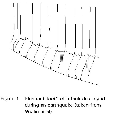
Different modes of tank failure have been observed after earthquakes:

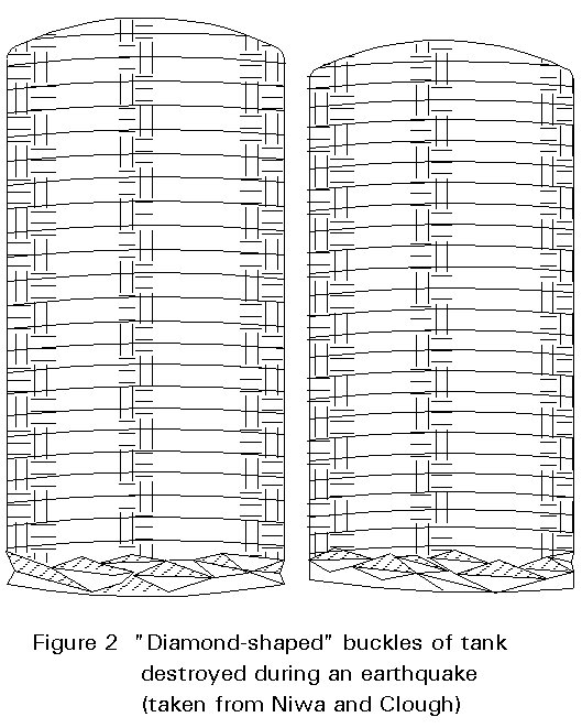
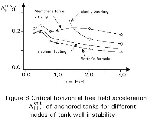
The most relevant types of tank damage are elastic-plastic buckling ("elephant footing") and elastic buckling of the tank wall.
To understand the behaviour of liquid storage tanks subjected to earthquake excitation, many research groups have been active in investigating the dynamic behaviour of liquid filled shells. The aim has been to develop methods for the earthquake resistant design of liquid storage tanks, and to provide codes for engineers engaged in the construction of liquid storage tanks. Such engineering approaches need to be based on consideration of the coupled dynamic system consisting of the elastic or elastic-plastic shell, the tank's liquid content, and the deformable foundation. It is a liquid-structure-soil interaction problem. Fundamental scientific findings were published by Housner [5], which allow estimation of the dynamic loads of rigid tanks resting on rigid foundations. A recent review of the engineering treatment of storage tanks under earthquake loading is presented by Rammerstorfer et al [6].
Recent engineering procedures, e.g. Fischer et al [7] and Veletsos and Tang [8], based on parametric studies have been published. They allow an earthquake resistant design of storage tanks typical for the petrochemical industry by simply using formulae and design charts.
There are many differences between current codes and recommendations for the earthquake resistant design of liquid storage tanks. Nevertheless, global procedures are similar, especially for anchored tanks. The design procedures can be divided into calculation of dynamically activated loads, and strength and stability analyses. The following summary outlines the essentials of the procedures:
× Calculation of the natural frequencies, damping values, and mode participation factors of the individual vibration modes.
× Calculation of the maximum acceleration response of the individual vibration modes (rigid motion of the "liquid column", interactive vibration of the flexible tank wall and liquid, sloshing vibration at the free surface), see Figure 3.
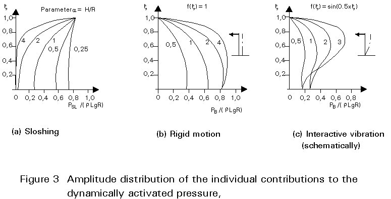
× Calculation of the maximum contributions to the overturning moment (corresponding to the individual vibration modes) due to the dynamically activated pressure caused by the horizontal earthquake excitation.
× Superposition of the contributions to the overturning moment and the contributions to the dynamically activated pressure caused by the horizontal excitation.
× Calculation and superposition of the contributions to the dynamically activated pressure caused by the vertical earthquake excitation.
× Superposition of pressure caused by the horizontal earthquake excitation with that caused by the vertical earthquake excitation with respect to different kinds of tank wall instability. Internal pressure is stabilising with respect to elastic buckling and destabilising in case of plastic buckling.
For tanks not anchored to the ground, non-linearities arise due to the unilateral contact between the base of the tank and its foundation in addition to non-linearities due to the elastic-plastic material behaviour. To build a tank without anchors is much cheaper because neither a special concrete foundation nor special anchors are needed. The dynamic behaviour of an unanchored tank is quite different from that of an anchored tank. Partial uplift of the tank bottom caused by the overturning moment leads to increased maximum axial compression forces in the tank wall. Hence, tank wall instabilities may occur at lower overturning moments.
Housner [9] proposed a simple procedure for rigid tanks which is based on the response spectrum method. Essential comments on the use of the response spectrum method for the calculation of the dynamic loads of liquid storage tanks are given by Scharf [10].
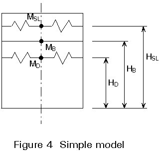
In the 1970s it became clear that the influence of deformations of the tank wall, which is a thin shell, must not be neglected and that the dynamic loads may be much higher than those of rigid tanks. Theoretical considerations led to a simple model (Figure 4) used in current codes for the calculation of the dynamic loads on earthquake - excited tanks in terms of the maximum overturning moment needed for the strength and stability analyses. Summarising, the dynamically activated pressure acting on the tank wall due to a horizontal excitation of a deformable cylindrical tank resting on a rigid soil is given by the superposition of four pressure components:
PSL is the "convective" pressure component due to the fundamental sloshing vibration of the liquid (circumferential wave number m=1).
PB is the "impulsive" pressure component due to the rigid body motion of the liquid which varies synchronously with the horizontal ground acceleration.
PD is the pressure component due to the fundamental, i.e. m = 1, interaction vibration of the shell and the liquid,
PD,m are the pressure components due to interaction vibrations with m ³ 2. These components which result from imperfections may be neglected with respect to the estimation of the overturning moment.
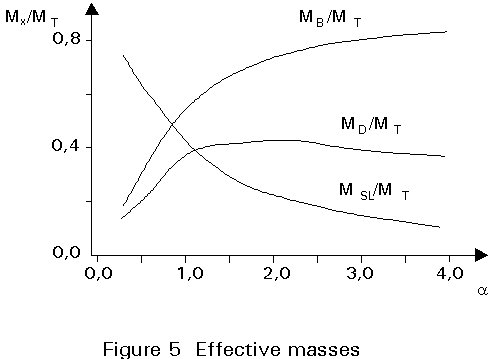
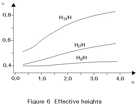
The maximum overturning moment is calculated by superposition of the individual contributions due to sloshing, rigid body motion, and fluid-shell interaction vibration. Different superposition rules, based on an SRSS superposition, have been proposed. In the above engineering approaches, formulae and diagrams are presented for estimating the natural frequencies and the individual masses and height in Figure 4 which depend mainly on a = H/R, a size parameter R or H, and the mass density of the liquid. These formulae and diagrams result from integration of the individual pressure contributions.
On this basis the maximum overturning moment resulting from the dynamically activated pressures acting on the tank wall (bottom pressure not included) can, according to Fischer et al [7], be estimated by:
MM = [(MSL ASL HSL)2 + (MB AB HB)2 + (MD AD HD)2]1/2 (1)
or alternatively, according to Haroun and Housner [11] by:
MM = [(MSL ASL HSL)2 + (MB AB HB + MD AD HD)2]1/2 (2)
where, for tanks designed according to DIN 4119, the ratio between effective masses (MSL, MB, MD, compare Figure 4) and the mass of the liquid content (MT) can be taken from Figure 5, and the corresponding heights from Figure 6.
ASL, AB and AD are the effective accelerations. They are the product of the corresponding spectral accelerations (taken from the response spectrum) and mode participation factors. The fundamental frequencies can, according to Fischer et al [7] be approximated by:
fSL = [1/(2p)] [1,84 g tanh (1,84 a)/R]1/2 cps (3)
fD = [E s1/3/(rLH)]1/2 / (2Fs (a)R)] cps (4)
with Fs = 0,157 a2 + a + 1,49 ; a = H/R (5)
and where
s1/3 is the wall thickness at H/3.
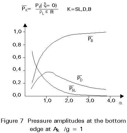
The pressure amplitudes at the bottom edge - values needed for the stability check and strength assessment of the tank wall - can be estimated by Figure 7.
The two-dimensional character of the horizontal earthquake action is discussed by Scharf [10]. It is shown that consideration of the one-dimensional acceleration is, in general, not sufficient. Relevant procedures are presented by Scharf [10].
The vertical component of the earthquake leads mainly to the excitation of axisymmetrical vibration modes. Again rigid body motion, interaction vibration of flexible shell and liquid as well as free surface sloshing, can be distinguished, see Fischer et al [7]. They can be estimated by simple formulae similar to the procedure described above, taking into account the radiation, i.e. geometrical, damping due to energy radiation by outrunning waves, see Seeber [12].
From these estimates, the strength analysis and the buckling check can be performed. The empirical formula developed by Rotter and Seide [13] for cylindrical shells under axial compression and internal pressure:
nxcrit = 0,605 (Es2/R) [1 - (pR/(ssy))2] *
* [1 - 1/(1,12 + k1,15] (sy/250 + k)/(1 + k),
where nxcrit is the critical axial membrane force
sy is the yield stress
p is the internal pressure
E is Young's modulus
k is R/(400s)
R is the tank radius
s is the thickness of tank wall (at the bottom)
leads to proper estimates. This result can be seen, for example in Figure 8 for the Friuli 1976 earthquake, for case of steel tanks for the petrochemical industry.
In the analysis of unanchored tanks, the investigation of the retaining action of the bottom plate is essential to obtain the increased axial membrane compression force in the tank wall.
Since a strongly non-linear (geometrical and material) fluid-structure-soil interaction and contact problem has to be solved, the calculation of the dynamic response of unanchored tanks is very complicated. Hence, no fully satisfactory models are available.
Clough [14] assumed that the uplifted tank rests, on the one hand, on a section of the circumference and, on the other hand, on the area of an eccentrically positioned circle, see Figure 9a.
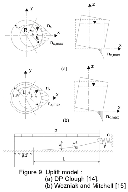
Wozniak and Mitchell [15] presented an improved uplift model taking the formation of plastic hinges in account, see Figure 9b.
A more sophisticated model is based on the "shell-spring model" for uplifting strips by Auli et al [16]. Friction between the bottom plate and the soil, as well as membrane forces in the bottom plate, were considered. The validity of the model was verified by experiments using Mylar model tanks, see Rammerstorfer et al [17].
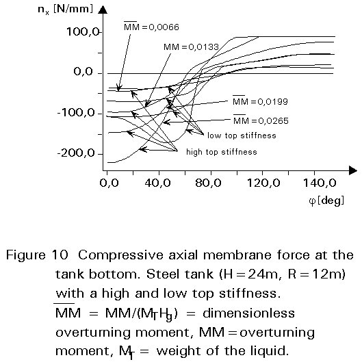
Results of comprehensive numerical analyses, Scharf [10], show a strong influence of the roof or top stiffness on the axial membrane compression force distribution. This fact has also been reported by Natsiavas [18] and Sakai et al [19]. Figure 10 shows the axial membrane force nx at the tank bottom for a tank with a low and a high top stiffness (roof or edge ring) at different earthquake intensities. For the tank with a high top stiffness, the maximum of the axial compression force lies on the axis of symmetry. For the tank with a low top stiffness two maxima exist, which lie beside the axis of symmetry. This phenomenon is not considered in most analytical models described above.
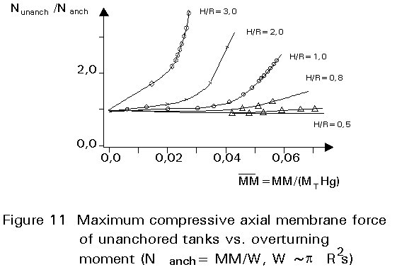
From results of parametric studies, a design chart has been developed which allows the estimation of the maximum axial membrane compression force at the tank bottom of unanchored tanks Nunanch, Scharf [10]. The chart is based on the maximum axial membrane compression force for anchored tanks Nanch (see Figure 11). It is concluded that the increase of the axial membrane compression force must not be neglected, especially in the case of "tall" tanks. The influence of the increased axial membrane compression force on different kinds of instabilities of tank walls is remarkable.
A procedure in which the non-linear character of the vibration of uplifting tanks is considered in Scharf [10] and Fischer et al [7].
Some of the existing codes and recommendations are listed below:
The procedures of TID 7024, API 650 and AWWA-D100-84 are compared by Bureau [20]. The codes were found to underestimate or to overestimate the dynamic response, depending on the distance from and magnitude of the earthquake.
This report gives a summary of the Austrian research project which deals with the earthquake resistant design of tanks. The scientific background of a design procedure is presented by the authors [7] and considers:
Wall deformations are considered in Japanese codes. Some recommendations for dealing with buckling are given. Uplift of the tank bottom edge is not taken into account adequately for unanchored tanks.
[1] Jennings, P.E. (Ed), "Engineering Features of the San Fernando Earthquake", EERI-71-02, pp. 434-470, California Institute of Technology, Pasadena, 1971.
[2] Wyllie, L.A., Bolt, B., Durkin, M.E., Gates, J.H., McCormick, D., Smith, P.D., Abrahamson, N., Castro, G., Escalante, L., Luft, R., Olson, R.S. and Vallenas, J., "The Chile Earthquake of March 3, 1985", Earthquake Spectra, Vol.2, No. 2, Chapter 5, pp. 373-409, 1986.
[3] Berz, G. "List of Major Natural Disasters, 1960-1987", Natural Hazards, Vol. 1, pp. 97-99, 1988.
[4] Nielsen, R., and Kiremidjian, A.S., "Damage to Oil Refineries from Major Earthquakes", Journal of Structural Engineering, ASCE, Vol. 112, pp. 1481-1491, 1986.
[5] Housner, G.W., "The Dynamic Behaviour of Water Tanks", Bulletin of the Seismological Society of America, Vol. 53, pp. 381-387, 1963.
[6] Rammerstorfer, F.G., Scharf, K. and Fischer, F.D., "Storage Tanks Under Earthquake Loading", Appl. Mech. Rev., Vol. 43, pp. 261-282, 1990.
[7] Fischer, F.D., Rammerstorfer, F.G. and Scharf, K., "Earthquake Resistant Design of Anchored and Unanchored Liquid Storage Tanks Under Three-Dimensional Earthquake Excitation", Structural Dynamics - Recent Advances, Schueller, G.I. (Ed), Chapter 5.1, pp. 317-371, Springer-Verlag, 1991.
[8] Veletsos, A.S., and Tang, Y., "Soil-Structure Interaction Effects for Vertically Excited Tanks", Proceedings of the 9th World Conference on Earthquake Engineering 9WCEE, Tokyo/Kyoto, Japan, Vol. VI, pp. 631-636, 1988.
[9] Housner, G.W., "Dynamic Pressure on Accelerated Fluid Containers", Bulletin of the Seismological Society of America, Vol. 47, No. 1, pp. 15-35, 1957.
[10] Scharf, K., "Beiträge zur Erfassung des Verhaltens von erdebenerregten, oberirdischen Tankbauwerken", Doctoral Thesis, Fortschritt-Berichte VDI, Reihe 4, Nr 97, VDI Verlag, Düsseldorf, FRG, 1990.
[11] Haroun, M.A. and Housner, G.W., "Earthquake Response of Deformable Liquid Storage Tanks", Journal of Applied Mechanics, ASME, Vol. 48, pp. 411-417, 1981.
[12] Seeber, R., "Das dynamische Verhalten fernerregter flüssigkeitsgefüllter Tankbauwerke auf elastischem Untergrund, Doctoral Thesis, Institute of Mechanics, University of Mining and Metallurgy, Leoben, Austria, 1988.
[13] Rotter, J.M. and Seide, P., "On the Design of Unstiffened Shells Subjected to an Axial Load and Internal Pressure, Proceedings of the ECCS Colloquium on Stability of Plate and Shell Structures, Ghent University, Belgium, pp. 539-548, 1987.
[14] Clough, D.P., "ExperimentaL Evaluation of Seismic Design Methods for Broad Cylindrical Tanks", UCB/EERC-77/10, University of California, Berkely, 1977.
[15] Wozniak, R.S. and Mitchell, W.W., "Basis of Seismic Design Provisions for Welded Steel Oil Storage Tanks", Proceedings of the Session of Advances in Storage Tank Design, API Refining Dept., pp. 485-493, 1978.
[16] Auli, W., Fischer, F.D. and Rammerstorfer, F.G., "Uplifting of Earthquake-Loaded Liquid-Filled Tanks", Proceedings of the Pressure Vessels and Piping Conference, ASME, PVP Vol. 98-7, pp. 71-85, 1985.
[17] Rammerstorfer, F.G., Billinger, W. and Fischer, F.D., "Stabilität flüssigkeitsgefüllter unverankerter Zylinderschalen auf schräger Unterlage, Zeitschrift für angewandte Mathematik und Mechanik ZAMM", Bd 68, T240-T243, 1988.
[18] Natsiavas, S., "Simplified Models for the Dynamic Response of Tall Unanchored Liquid Containers", Proceedings of the Pressure Vessels and Piping Conference, ASME, PVP Vol. 157, pp. 15-21, 1989.
[19] Sakai, F., Isoe, A., Hirakawa, H. and Mentani, Y., "Experimental Study on Uplifting Behaviour of Flat-based Liquid Storage Tanks Without Anchors", Proceedings of the 9th World Conference on Earthquake Engineering 9WCEE, Tokyo/Kyoto, Japan, Vol. VI, pp. 649-654, 1988.
[20] Bureau, G., "Seismic Design Guidelines for Liquid Storage Tanks: Applicability and Limitations", Proceedings of the 4th International Conference on Soil Dynamics and Earthquake Engineering, Mexico, City, Mexico, pp. 343-354, 1989.
[21] Niwa, A. and Clough, R.W., "Buckling of Cylindrical Liquid-Storage Tanks Under Earthquake Loading", Earthquake Engineering and Structural Dynamics, Vol. 10, pp. 107-122, 1982.