ESDEP WG 17
SEISMIC DESIGN
To give basic knowledge about the ductility resources of steel members and connections under cyclic loading.
None.
None.
After a brief introduction and a description of the cyclic behaviour of the material this lecture examines the ECCS recommended testing procedure for assessing the behaviour of structural steel elements under cyclic loads in the context of earthquake resistant design. A description of the loading history and the interpretative parameters of the recommended testing procedure and their use is also presented.
An overview of recent European research work is given. Experimental results on the cyclic behaviour of bracing elements, beams, columns, beam-to-column connections and shear links for eccentrically braced steel frames are presented to illustrate typical behaviour and physical phenomena related to failure modes and deterioration of resistance. A comparison between the cyclic behaviour of different detailed connections (fully welded joints, bolted joints using angles, cover plates, flanges) is discussed.
Today steel rolled products, such as H or tube sections, are available in a wide variety of types and dimensions, larger than in the past. They may be used to produce a wide range of structural elements and connections.
Steel elements have the advantage that huge elements can easily be constructed. They may be considered the most appropriate building material to ensure the seismic resistance of large structures. The performance and ductility of the structural elements and connections may be affected by many factors.
Structural steel elements often have high slenderness and slender cross-section due to high strength, and various types of buckling may occur, such as flexural buckling of the whole element, lateral-torsional buckling and local buckling of plate elements constituting the element.
In the Eurocodes, cross-sections are classified with respect to the proportions and loading conditions of each of their compression elements. Compression elements include every element of the cross-section which is either totally or partially in compression. Under cyclic loading the increase of the width-to-thickness ratio of the compression elements lowers the resistance, the ductility and the dissipated energy arising in the various types of buckling.
The occurrence of buckling brings a sudden reduction of the load-bearing resistance of the member. Even when buckling does not cause the immediate failure of the element, careful consideration should be given in design to the prevention of buckling because the response of the structure to an earthquake often becomes unstable due to the buckling of some elements.
In addition to analysis of the individual elements, the stability of the frames as a whole should also be analysed. In general second order effects included in the global analysis of sway frames produce a progressive decrease of resistance and a reduction of the dissipated energy and ductility. For that reason, the second order effects have always led to an overdimensioning of columns for frame-type buildings erected in seismic zones.
Seismic actions produce deformations with relatively few repetitions of the action. Deformations of fairly large amplitude occur at fairly low speeds. These deformations exhibit cyclic characteristics which may produce low cycle fatigue phenomena of structural elements and connections but rarely their failure. However, the possibility of damage from element failure should be considered in design against external cyclic loadings such as those produced by earthquakes.
Over the last twenty years tests have been performed in universities and research centres to obtain a better understanding of the seismic behaviour of structural steel elements and to characterise their ability to deform in the inelastic range. However, the testing procedures and the interpretative parameters of the tests have differed from one researcher to another, making qualitative and quantitative comparison difficult in some cases.
The European Convention for Constructional Steelwork (ECCS), through its Technical Committee 1 - Structural Safety and Loadings [1], has suggested a testing procedure for assessing the behaviour of structural steel subassemblages under cyclic loads [1]. This procedure is intended to be a defined method of experimental testing for structural elements or complete structures such that comparisons of results obtained by different authors are possible. The procedure is also intended to enable the assessment of the seismic behaviour of steel elements based on cyclic quasi-static tests using a specified loading history.
In seismic design it is very important to assess the ability of a structure to develop and maintain its bearing resistance in the inelastic range. A measure of this ability is ductility, which may be referred to the material itself, to a structural element, or to a whole structure. These three kinds of ductility are very different in their numerical values, and each one plays a significant role in seismic design.
Material ductility - me, measures the ability of the material to undergo large plastic deformations. A high value of me characterises a ductile material, a low value a brittle one.
Structural element or joint ductility - mq , characterises the behaviour of a member or joint, and particularly its ability to transmit stresses in the elastoplastic range without loss of resistance. For instances a frame structure cannot show a ductile behaviour if the plastic hinges are not able to redistribute the bending components.
Structural ductility - md , is an index of the global behaviour of the structure, i.e. the ability of a structure to deform in the inelastic range after some of its parts have exceeded their linear elastic range.
The ductilities me, mq and md must meet the condition:
me > mq > md
The steel used in an earthquake resistant structure must, of course, be of good quality. In addition to the general requirements for the material, the steel must have adequate ductility.
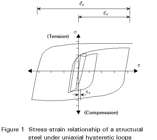
Figure 1 shows the stress-strain relationship of a structural steel under uniaxial hysteretic loops. In the first loading, the upper yield point, the lower yield point, the plateau and strain hardening appear clearly. In subsequent loadings, these properties disappear and the proportional limit markedly decreases due to the well-known Bauschinger effect.
Steels are usually considered to possess such prominent properties as yield point, plateau and strain hardening. For repeated loading beyond the elastic range, however, the stress-strain diagram with no plateau should be applied instead. Attention should be given to the possibility that the reduction of the proportional limit in each loading cycle may cause direct structural failure (for instance, buckling), increase of deformations and reduction of rigidity of structural elements, connections and cross-sections of elements.
Steel is an alloy of iron with carbon and various other elements. The carbon exerts the most significant effects on the microstructure of the material and its properties. Changes in the carbon percentage affect the strength, toughness and ductility of the steel.
Steels normally used in structures are excellent materials possessing a high ductility in the direction of rolling. Low steel grades of steel show better ductility than high grades.
The ductility of steel may be described as its post-elastic behaviour and may be measured, provided that the stress-strain relationship is known, as the ratio:
ductility = (deformation at failure) / (deformation at yield)
The numerical value of ductility is usually represented by the ductility factor, me, and depends on the origin considered for the deformation at failure. In general it can be defined by the ratio of the maximum deformation at the beginning of the cycle, eu, to the yield deformation, ey:
me = eu / ey
For cyclic loading and for a specified loading history, eu may be defined as the maximum deformation from the initially undeformed material eu¢ , or the deformation from the beginning of a cycle to the new maximum eu" (Figure 1). The last definition appears more meaningful for the assessment of cyclic behaviour.
The ductility in the material is desirable and necessary since the ductility of structural elements and of whole structures depends on the material characteristics. However, the possibility of brittle behaviour must be carefully guarded against by proper detailing and good workmanship.
The area within the hysteresis loop corresponds to the dissipated energy of the loop.
Various types of loading histories have been idealised in cyclic tests to evaluate the resistance-deformation characteristics of structural subassemblages. The most commonly used are (Figure 2):
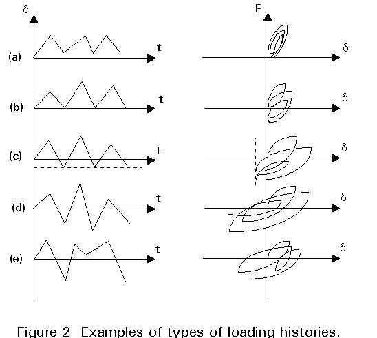
(a) no force reversal.
(b) force (F) reversal, but no deformation (d) reversal.
(c) partial deformation reversals.
(d) full deformation reversals.
(e) random.
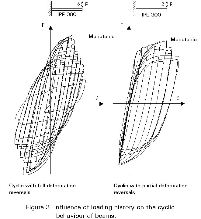
The type of load reversal has an important influence on the cyclic behaviour. Full deformation reversals cause more deterioration of the resistance of the element than partial deformation reversals, see Figure 3. Cyclic loadings produce much more deterioration of the resistance than monotonic loadings.
The selection of the loading history to use in the assessment of the seismic resistance of steel subassemblages is a very difficult task because it is impossible to know the real loading history in future earthquakes. However certain factors can be taken into account in choosing a loading history.
In general, displacement increase should be preferred to load increase because the resistance of a structural element may decrease after a few cycles due to buckling phenomena for instance. In this case, if load increase is applied the test cannot be controlled and it is probably best to discontinue it. However, it may be of interest to proceed with the test considering that the element is only a part of the structure and its decrease in resistance does not necessarily mean an important decrease in resistance for the structure.
As indicated above, full deformation reversal causes more deterioration of resistance than partial deformation reversals. Full deformation reversal is probably the most generally used loading for assessing the resistance to damage of the anti-seismic parts of a structure. The type of reversal used in tests however should be defined considering that the structural element is part of the whole structure and should be designed to resist both static and seismic actions.
The number of cycles at a constant maximum displacement should also be defined. The number of repetitions defined at the same displacement should not be too high in order to avoid low cycle fatigue phenomena, since the number of high peaks of displacement caused by real earthquakes is generally low.
The procedure for assessing the behaviour of structural steel elements under cyclic loads recommended by the ECCS [1] can be applied to plane or three dimensional tests and may include preliminary monotonic displacement tests. This procedure is designated the complete testing procedure. If monotonic tests are omitted it is designated the short testing procedure.
This procedure includes three tests performed on different specimens. The first and second tests impose displacement increasing monotonically in the tension and in the compression range respectively. The positive and the negative reference elastic load Fy and the corresponding reference elastic displacement dy are obtained from the recorded force-displacement curve. The reference elastic load is defined as the intersection between the tangent modulus Et at the origin of the force-displacement curve and the tangent that has a slope of Et/10 as indicated on Figure 4c.
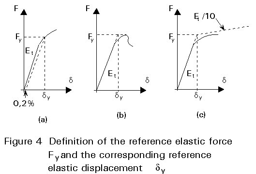
Other conventional definitions of Fy may be used, such as (a) the value corresponding to the 0,2% offset load at some point in the tested specimen (Figure 4a), or (b) the maximum load (Figure 4b). Definition (a) ignores the post-elastic reserves of the specimen and definition (b), in spite of its interest in the buckling context, may correspond to exaggerated deformation of the flexural behaviour of beams or joints.
The definition of Fy recommended by the ECCS (Figure 4c) covers many cases and types of behaviour and avoids some disadvantages of the definitions (a) and (b).
The third test is a cyclic test with increasing displacement as follows:
The end of the test is not defined beforehand. For research purposes the test will probably be continued as far as possible in order to obtain the maximum information. On the other hand a design engineer will probably stop the test as soon as the code requirements are reached.
Several problems are raised when it is necessary to compare different test results due to the diversity of the interpretative parameters used.
The recommendations of the ECCS use a standardisation of the interpretative parameters which are established in ratios which are meaningful to the engineer [1]. The suggested parameters are normalised with reference to those corresponding to a linear elastic-ideal plastic behaviour.
Since the behaviour of the element in the tension and in the compression range may be different, the parameters are evaluated in these two ranges. The quantities used in the ratios are deduced from the force-displacement curve and are obtained for cycles with displacements larger than the reference elastic displacement. The proposed parameters for a typical cycle (Figure 5) are:
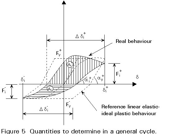
yi+= Ddi+/ [di+ + di- - dy-] yi-= Ddi-/ [di- + di+ - dy+]
ei+= Fi+/ Fy+ ei-= Fi-/ Fy-
xi+= tg ai+/ tg ay+ xi-= tg ai-/ tg ay-
hi+= Ai+/ [di+ + di- - dy+ - dy-]Fy+
where
di+ (di-) is the value of the maximum positive (negative) displacement in the ith cycle.
dy+ (dy-) is the value of the positive (negative) reference elastic displacement.
Ddi+ (Ddi-) is the value of the maximum displacement in the positive (negative) force range in the ith cycle.
Fi+ (Fi-) is the value of the positive (negative) force corresponding to the di+ (di-) in the ith cycle.
Fy+ (Fy-) is the value of the positive (negative) reference elastic force.
tg+ai(tg-ai) is the value of the slope of the tangent to the force-displacement curve when F changes from negative (positive) to positive (negative) at the ith cycle.
tg+ay(tg-ay) is the value of the slope of the tangent at the origin of the force-displacement curve for increase in positive (negative) direction.
Ai+ (Ai-) is the area under the positive (negative) force range of the half cycle in the force-displacement curve.
In general the behaviour of the element is better when its behaviour is near to the reference linear elastic-ideal plastic behaviour (values of parameters near to one).
Small values of the parameters, i.e. much less than 1, may be assumed as an index of the end of the test because they indicate large losses of ductility, resistance, rigidity and absorbed energy.
The parameters proposed by the ECCS have the advantage of assisting the quantitative analysis of the cyclic behaviour of structural elements [1]. They can also be considered as practical parameters for the definition of code acceptance criteria.
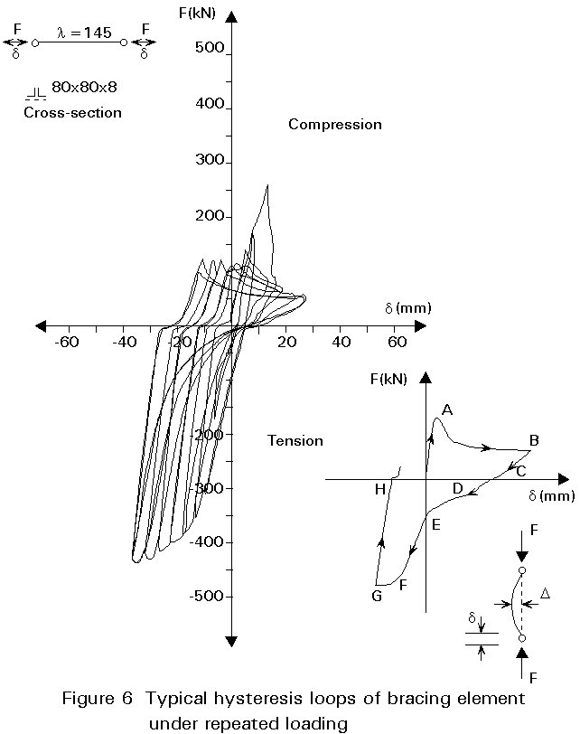
A typical plastic hysteretic behaviour of a bracing element under repeated loading is shown in Figure 6. Slide 1 shows its mode of failure. The force-displacement curve was obtained from experiment, in which an element made up of back-to-back angles 80 x 80 x 8 and slenderness ratio of 145 was subjected through pinned ends to repeated tension and compression. The strain amplitude was gradually increased in each loading cycle approximately following the ECCS short testing procedure [1].

Slide 1 : Mode of failure of a bracing element made up of back-to-back angles 80 x 80 x 8 and slenderness ratio of 145.
The initial buckling load corresponds to point A. Beyond point A on the force-displacement curve, the bracing element suffers a considerably loss of resistance as it buckles. This phase of the hysteretic behaviour A-B is dominated by the plastic interaction between the bending of the brace element due to the P-D effect induced by the compressive force. It is characterised by large lateral deflections and decreasing load. If the increment in the displacement is reversed, the force-displacement curve corresponds to the elastic recovery B-C with a brace lengthening C-E. In the case of bolted connections, a slip occurs in the force-displacement curve, zone C-D. In zone E-F a plastic interaction of axial force and bending moment occur with a decrease of the lateral deflection. At point F the element is fully straightened. The zone F-G is characterised by the plastic elongation of the element. Reversing the direction of the displacement results in the elastic unloading of the brace, zone G-H.
Figure 6 also shows a decrease of the ultimate compressive load with the application of the cyclic displacement, as a consequence of the Bauschinger effect. This decrease can also be a consequence of the brace curvature. In general, after an initial buckling cycle, the brace develops a residual curvature which is not completely removed by the subsequent tensile yielding. The brace behaves as an element with an initial curvature.
The hysteretic behaviour of a bracing element is affected by its slenderness ratio. Braces with small slenderness ratio absorb more energy than more slender ones, as can be seen by comparing their hysteresis loops. In general, bracing elements with large slenderness ratios show a more rapid deterioration in their compressive bearing resistance than those with smaller ratios.
For bracing elements for which the strength in compression is accounted for in the evaluation of the lateral stability of the frame (K bracing for instance), it is advisable to limit the reference slenderness
(![]() ) of the brace to values in the range 1,0 - 1,5.
) of the brace to values in the range 1,0 - 1,5.
![]() is defined in Eurocode 3 [2] as:
is defined in Eurocode 3 [2] as:
![]() =
= ![]()
where Nc is the compression resistance and Ncr is the Euler critical load. For the above values of
![]() , mean values for slenderness l are equal to 94-140 for steels Fe E 235 and 76-114 for steels Fe E 355. In general no requirements are necessary for X bracing or truss bracing because only the tension diagonal is accounted for in the evaluation of the seismic resistance.
, mean values for slenderness l are equal to 94-140 for steels Fe E 235 and 76-114 for steels Fe E 355. In general no requirements are necessary for X bracing or truss bracing because only the tension diagonal is accounted for in the evaluation of the seismic resistance.
According to Eurocode 8 [3] the connections of bracing elements to other elements shall fulfil the overstrength condition:
Rd ³ 1,20 Npd
where Rd is the resistance of the connection and Npd is the ultimate resistance of the connected part according to Eurocode 3 [2]. This condition ensures that the connected element fails before the connection.
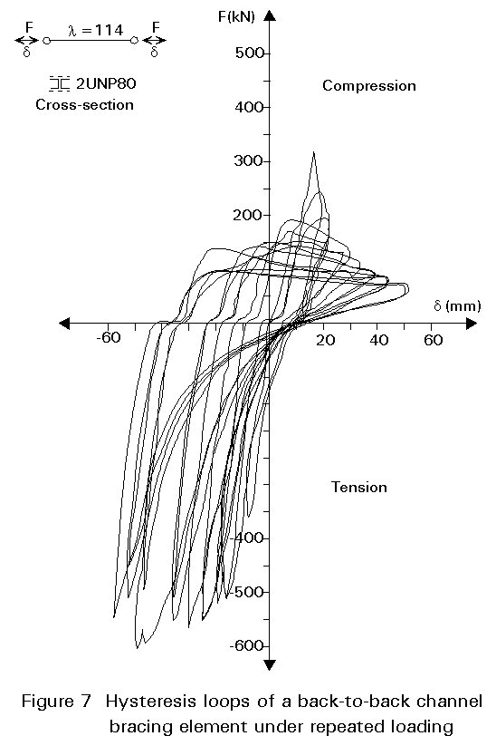
The hysteretic behaviour of the brace is affected to some extent by the shape of the cross-section. Figure 7 shows the hysteresis loops of a channel bracing element under repeated loading. Slide 2 shows its mode of failure. The cross-sectional shape affects the susceptibility of the brace to lateral-torsional buckling and local buckling and, as a result, the compressive carrying resistance.

Slide 2 : Mode of failure of a channel bracing element under repeated loading. The cross-section shape affects the susceptibility of the brace to lateral-torsional buckling and local buckling and, as a result, the compressive resistance.
In general, rolled steel sections as currently produced exhibit local buckling at extremely large lateral displacements. Experimental studies performed by several authors indicate progressively poorer performance of cross-sectional shapes in the sequence: tubes, wide flanges, tees, double channels and double angles. The poor performance of tees and double angles in comparison with tubes and wide flanges can be assigned to their geometric proportions and single symmetry. Tees and double angles buckle in the direction perpendicular to their axis of symmetry causing flexural and lateral-torsional buckling. Consequently they have a lower carrying resistance than that which would develop in pure flexural buckling.
Built-up braces should be designed as a single element. It is important to observe the structural rules for detailing the design in order to avoid early buckling of individual elements under low load.
The reinforcement of support points must not be forgotten in order that bracing elements may fulfil their expected purpose. If the ends of an element can displace easily, the stability of the whole building must be considered. Generally, bracing elements are connected by a gusset plate which has a low flexural rigidity. For this reason, the gusset plate may require reinforcement to increase it's bending resistance.
Figure 8 shows a force-displacement hysteresis curve obtained from an experiment on an I cantilever beam subjected to repeated loading according to the ECCS short testing procedure [1].
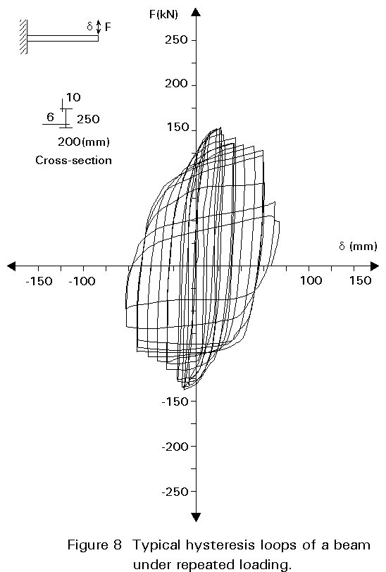
Experimental investigations carried out on cantilever beams under repeated and reversing loading have shown that the development of local buckling in the flanges does not signal an immediate loss of the moment resistance. The beams are able to sustain loads substantially higher than those that cause initial flange buckling. This behaviour is attributed to the considerable post-buckling strength of the plate elements. However, after the occurrence of the maximum load in the subsequent load cycles, the moment resistance deteriorates. This deterioration is higher with increasing width-thickness ratio (b/t) of the flanges as a consequence of the early occurrence of local instability in the flange elements.
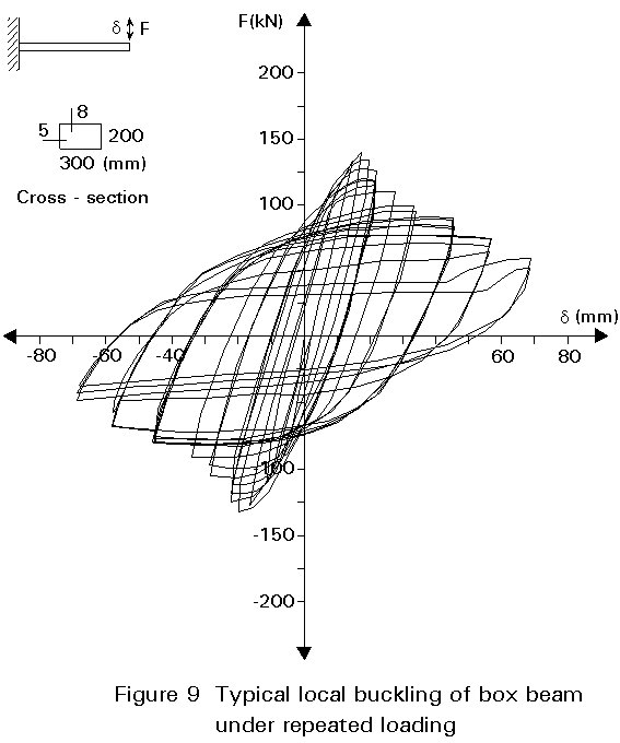
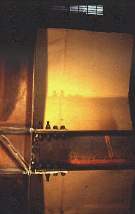
The severe distortions of the flanges tend to induce torsional displacement of the section (Slides 3 and 4). They are associated with a lower load that would develop in pure flexural buckling. This effect is likely to contribute to the somewhat poorer performance of H and I beams as compared to box shaped cross-sections as shown in Figure 9 and Slides 5 and 6. For this reason, unless supports in the lateral direction are provided, the use of a box section is preferable. Similarly the behaviour of truss beams is improved by using steel tube with high torsional rigidity as flange elements.
Slide 3 : The severe distortions of the flanges of H and I sections tend to induce torsional displacement of the section.
Slide 4 : The severe distortions of the flanges of H and I sections tend to induce torsional displacement of the section.
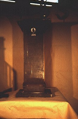
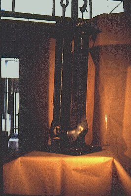
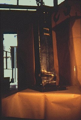
Slide 5 : Box sections are torsionally stiff and are therefore much less susceptible to lateral-torsional buckling.

Slide 6 : Box sections are torsionally stiff and are therefore much less susceptible to lateral-torsional buckling.
To allow the development of a plastic hinge with a very good rotational capacity in rolled beams with H and I cross-section, the following condition of the flange is required (b flange width, t flange thickness):

This condition is generally satisfied by rolled steel sections currently available. This limiting ratio ensures that the flanges can be compressed uniformly without buckling up to strains in the strain hardening range of the material. The increase of stability is in general accompanied by an increase of the ductility of the beam.
Limited information is available on the cyclic behaviour of beams with b/t ratios exceeding the limiting value. However, the cyclic behaviour and strength of these beams is similar to those with b/t ratio of flanges less than this limit. However flange buckling has been observed at a moment slightly higher than the plastic moment.
Further research is necessary in order to verify the limiting width-thickness ratio for plates under cyclic bending.
For beams with cross-sections having different ultimate characteristics in the two directions, the rotational capacity and the ductility factor may also be different in the two directions. T-sections, for example, have different rotational capacities in the two principal directions of the bending.
In frames, in order to guarantee sufficient hysteresis rotation capacity of beams under the full plastic moment action effects, the following inequalities shall be verified at the locations where the formation of hinges is expected according to Eurocode 8 [3]:
![]() £ 1,0
£ 1,0
![]()
![]()
where
N, M are the action effects taking account of the behaviour factor q.
Npd, Mpd are the ultimate resistances according to Eurocode 3.
Vo is the shear force due vertical loads.
VM is the shear force due to the resisting moments of the beam and its extremities.
Vpd is the shear resistance of the beam according to Eurocode 3 [2].
Some experimental information on the behaviour of columns under repeated bending with a constant axial force is available. It shows that, where there is a large axial force, the height of the first loading curve is low and the gradients of the curves are negative after the attainment of the maximum load in each loading cycle (Figure 10). This effect is commonly referred to as the P-D effect. It should be noted, however, that the load-carrying resistance increases in each loading cycle because of the accumulated compression strain hardening under repeated bending and constant force. The strain accumulation caused by cyclic bending would reduce the rotation capacity of the section. The extent of the reduction has not been thoroughly investigated. It is not yet known the extent to which this reduction affects the load-carrying resistance of columns.
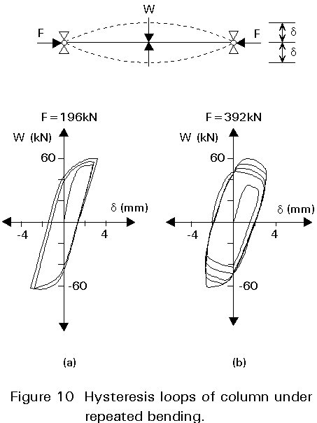
The existence of axial force in the columns leads to a more rapid decay of the load-carrying resistance owing to more extensive buckling in comparison to beams.
There are many types and varieties of connections, and each has different rotational characteristics that affect the frame behaviour. Butt welding, fillet welding, bolting, and riveting may be employed for aseismic connections, either individually or in combination. As fully bolted or riveted connections tend to be large and expensive, fully welded connections or a combination of welding and bolting are the most frequently used. Bolts have the advantage of providing more damping to frames than welds.
Connections should be designed to make fabrication and erection of the framework as simple and rapid as possible.
Conclusive design criteria for beam-to-column joints are not yet available for seismic conditions. Until the recent past relatively few cyclic load tests had been performed on joints commonly used in Europe. At present many experimental investigations are in progress in different European laboratories. They deal with cyclic behaviour of rigid and semi-rigid joints, both for bare steel and composite constructions.
Preliminary research to investigate the influence of detailing of the joint was performed by Ballio, Mazzolani et al on fourteen specimens [4, 5]. The connection types were in compliance with the technology commonly used in Europe for rigid and semi-rigid joints. The experiments followed the ECCS recommended testing procedure for short tests [1]. The specimens were grouped into four main categories (Figure 11):
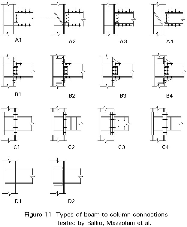
Type A - This type of connection is made using three plate splices which are welded to the column and bolted to the flanges and to the web of the beam. The basic type A1 is varied by the introduction of diagonal stiffeners in the column web (A2, A4) or reinforcing plates in the beam flanges (A3, A4).
Type B - Angle splices are bolted both to the column and to the beam. The basic type B1 is varied by stiffening the column (B2, B4) or the angle splices connected to the beam flanges (B3 - B4).
Type C - End plate joints with rigid column stub. Variations from the basic type C1 are derived by introducing stiffeners in the beam web (C2, C3, C4) or increasing the thickness of the end plate (C3, C4).
Type D - Fully welded connections of basic type (D1) or varied with reinforcing plates on the column web (D2).
Comparison between the results (Figure 12) indicates the role played by the detailing of the connections under alternating loading conditions.
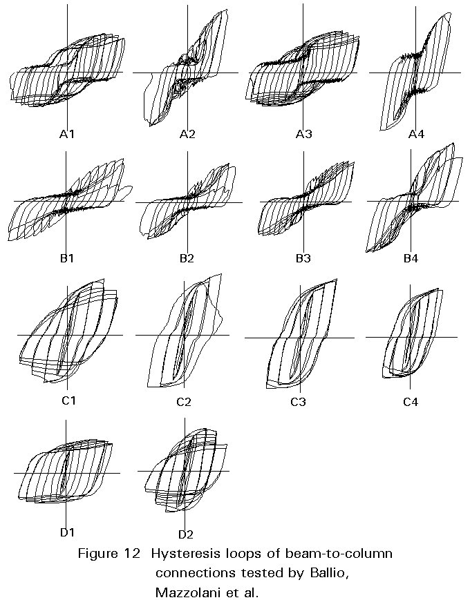
Comparing for instance A4 to A3, the introduction of a diagonal plate to stiffen the central panel of the column (Slides 7 and 8) reduced the energy dissipated, increased the strength, and the collapse became brittle because the failure occurred at the maximum load. The opposite behaviour was found for A1 and A3 which collapsed in a ductile manner.
Slide 7 : The introduction of a diagonal plate to stiffen the central panel of the column reduces the energy dissipated, increases the strength, and results in brittle collapse because the failure occurs at maximum load.
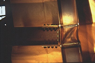
Slide 8 : The introduction of a diagonal plate to stiffen the central panel of the column reduces the energy dissipated, increases the strength, and results in brittle collapse because the failure occurs at maximum load.
The stiffening elements placed under the column flange to control the deformation produced by the tension force of the angle profile bolts (Slides 9 and 10) increased the resistance of connection B4 compared to B3, for instance. The introduction of a triangular plate in the angle connecting the beam and column flange also produced an increase of energy and resistance.
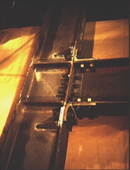
Slide 9 : Stiffening elements placed under the column flange to control the deformation produced by the tension force of the angle profile bolts increases the resistance of the connection.

Slide 10 : Stiffening elements placed under the column flange to control the deformation produced by the tension force of the angle profile bolts increases the resistance of the connection.
The addition of the beam web-flange stiffeners (compare C2 to C1 in Slides 11 and 12) reduced the energy and increased the resistance. The increase of thickness of the end-plate in C3 and C4 or the introduction of partial or full stiffening plates in the beam improved the load level, but not sufficiently to compensate for the energy dissipated by C1.

Slide 11 : The addition of beam web-flange stiffeners reduces the energy and increases the resistance.
Slide 12 : The addition of beam web-flange stiffeners reduces the energy and increases the resistance.
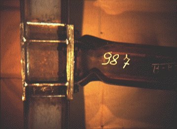
The stiffening of the column panel in D2 produced a decrease of energy absorption and an increase of load level reached in comparison to D1 (Slides 13 and 14).

Slide 13 : The stiffening of the column panel produces a decrease of energy absorption and an increase of load level.

Slide 14 : The stiffening of the column panel produces a decrease of energy absorption and an increase of load level.
Based on these tests, some general qualitative indications regarding detailing may be drawn:
For this type of connection the plastic rotation of the beam is mainly developed by the extension of plastic deformation near the connection. Generally, in order to control the extension of the plastic region in the element in the vicinity of the connection, the beam-to-column connection must have an ultimate bending moment which is greater than the full bending resistance of the attached element. For this reason Eurocode 8 [3] requires that the resistance of the connection be greater than the resistance of the adjacent connected element:
Rd ³ 1,20 Rfy
where Rd is the resistance of the connection according to Eurocode 3 [2] and Rfy is the yielding resistance of the connected part. Connections made by means of butt-welds or full penetration groove welds are deemed to satisfy this overstrength criterion.
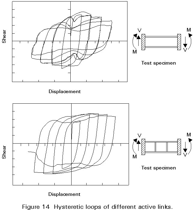
Beam-to-column connections are one of the most common types of connections in steelwork. However other types of connections may occur in steel frames. In eccentrically braced frames (Figure 13) the axial forces in the brace are transferred to another brace, or to a column through shear and bending in a short segment of beam, usually called the active link. Its behaviour is strongly dependent on its length. If it is sufficiently long, plastic moment hinges form at both ends of the link. On the other hand, if this link is short it tends to yield in shear with smaller end moments.
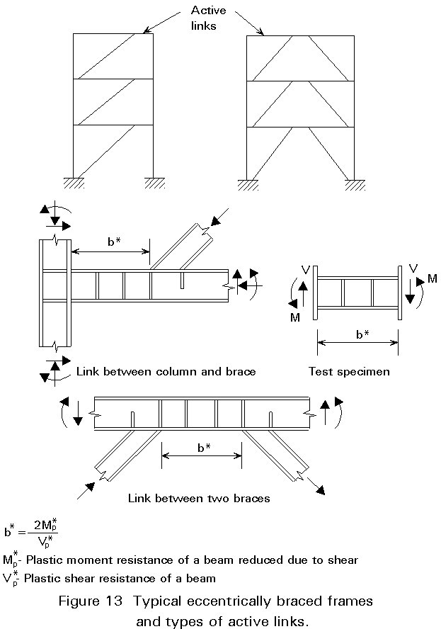
Active links equal to or shorter than b* (Figure 13) will yield predominantly in shear, and are called shear links. Links that are somewhat longer experience substantial moment-shear interaction. The end moments of the long links will approach the plastic moment resistance of the beam, and moment hinges will form at the ends of the links. Such links are referred to as moment links.
For moment links a large increase in shear can take place with only a small change in moment. Conversely, for shear links the shear resistance remains essentially constant for a considerable range of end moment.
Based on the results of the investigation performed by Popov et al on the seismic behaviour of active links [6, 7, 8], some general conclusions can be drawn from the hysteretic behaviour of this type of connection:
According to Eurocode 8 [3], in order to guarantee the formation of a shear mechanism in the active link with full deformation capacity, the full resistances to the action-effects other than shear are restricted to values as follows:
![]() £ 1,00
£ 1,00
![]() £ 0,70
£ 0,70
![]() £ 0,15
£ 0,15
where V, M and N are the action-effects and the index pd denotes the respective ultimate resistance.
[1] Recommended Testing Procedure for Assessing the Behaviour of Structural Steel Elements under Cyclic Loads ECCS Publication No45, 1986.
[2] Eurocode 3: "Design of Steel Structures": ENV 1993-1-1: Part 1.1, General rules and rules for buildings, CEN, 1992.
[3] Eurocode 8: "Structures in Seismic Regions - Design", CEN (in preparation).
[4] Ballio, G., Calado, L., De Martino, A., Faella, C., Mazzolani, F. M. (1987) Cyclic Behaviour of Steel Beam to Column Joints: Experimental Research, Costruzioni Metalliche No. 2. pp 69-90.
[5] Popov, E. (1980) Seismic Behaviour of Structural Subassemblages. ASCE Journal of the Structural Division, ST7, Page 1451-1470.
[6] Popov, E. (1980) An Update on Eccentric Seismic Bracing. AISC Engineering Journal n. 3, Page 70-71.
[7] Popov, E. and Roeder, C. (1978) Design of Eccentrically Braced Steel Frame. AISC Engineering Journal, n.3, Page 77-81.