ESDEP WG 1B
STEEL CONSTRUCTION:
INTRODUCTION TO DESIGN
To outline the principal features of the design of special industrial buildings.
None.
Lecture 1B.5.1: Introduction to the Design of Simple Industrial Buildings
Special industrial buildings are of two kinds - those which are of unusual construction and those which are designed for a special industry. Several features, such as handling methods, maintenance and fire protection, are briefly discussed. Examples of special buildings, e.g. power stations, hangers, are presented.
Special industrial buildings are of two kinds - those which are of unusual construction and those which are designed for a special industry. The main characteristic of such buildings is that they are invariably designed for a particular purpose or process, and are consequently virtually impossible to adapt for another kind of use.
Among the former are industrial buildings which, for reasons of prestige rather than economy, utilise unusual structural forms which provide architectural expression and thereby contribute to the visual quality of the building. Because buildings of this kind are unique they cannot be considered generically. Some examples are briefly described later in this lecture.
Among buildings designed for specific industries are heavy engineering works, aircraft hangars, power stations, process plants, steel rolling mills and breweries. Many of these buildings have similar features which are considered in principle below.
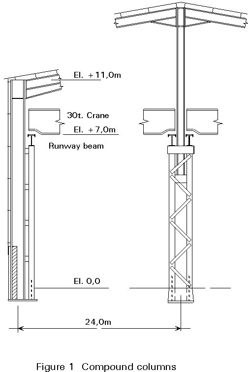
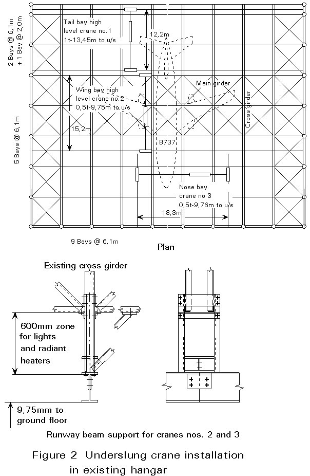
Overhead cranes with capacities of 10 tonnes and more are a characteristic of heavy engineering works and power stations. They require the support of compound columns and runway beams to carry the vertical and surge loads (Figure 1). Light overhead cranes with capacities of 1 to 5 tonnes, are a characteristic of aircraft hangars and light industries. They can be attached to the roof structure and be designed for multiple supports for wide coverage, or they can be arranged to transfer laterally from bay to bay (Figure 2). Roof flexibility may become important for roof-mounted cranes used for assembly.
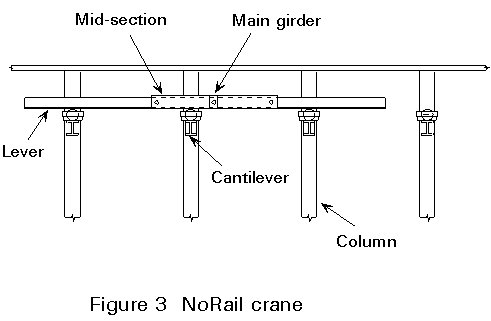
Some years ago, so-called NoRail cranes were developed.
The NoRail crane concept inverts the overhead crane principle. Short rails are mounted in the endtrucks of the crane. These rails run along a series of stationary wheels. The rails are designed to be somewhat longer than the maximum distance between three adjacent support points, so that the crane is always supported by at least two wheels on each side (Figure 3). As a result of this design, the long conventional crane track becomes superfluous. The benefits of this innovative design arise both in cost savings (up to 20%) on the steel structure of the building and in material handling. Crane travel "tracks" that cross each other are feasible.
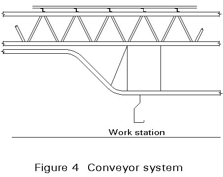
Conveyors can be either floor or roof mounted. Conveyors for assembly purposes may carry appreciable weights, and are of necessity suspended from the roof (Figure 4). Power roller conveyors are also used for transport of bulky items and are usually floor mounted.
As a result of advances in design, motorised floor transport vehicles including fork-lift and pallet trucks are now very common. The main influence they have on design is on the floor quality and on headroom.
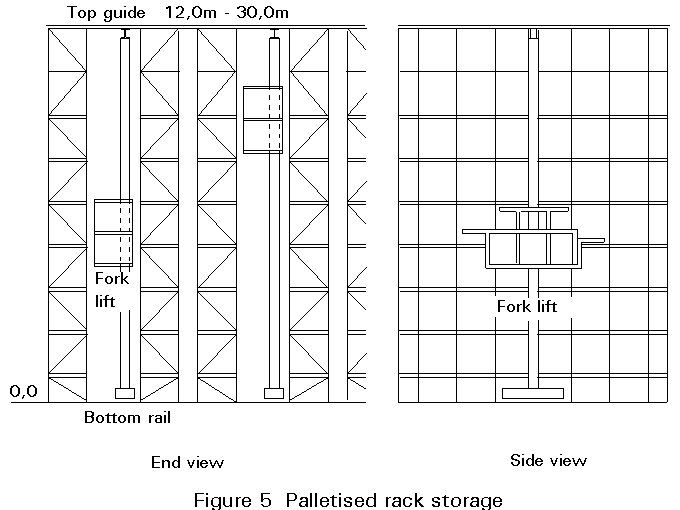
Automated pallet stacking by fork-lift trucks of specialised design may require very stringent control of fabrication and erection of the stacking racks. The racks may be incorporated in the structure of the building (Figure 5).
Few industries now have particular needs in respect of daylighting, since shift work is often provided for. Sidewall and roof daylighting is usually described as a percentage of the plan area, 5% giving sufficient light for bulk storage, 20% for a working process. Since artificial lighting is usually employed to establish a consistent high level of illumination, daylighting may be provided for visual comfort or for architectural effect.
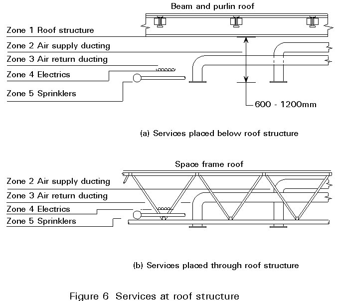
The amount of services can vary in different parts of a building, from an exacting standard of air conditioning appropriate to a "clean room" to extensive process ductwork. The support and passage of services can be facilitated or hindered by the roof construction (Figure 6). The heating of high single-storey structures is always a problem, particularly when fire safety places stringent control on the temperature of the heat source. Inevitably provisions for cranage, lighting, heating and services such as air and electric power, will conflict. They each influence the structural design. Sometimes, if services are particularly extensive, it is advantageous to use a structural form which provides abundant support for services.
Whilst it is usual in advanced factory units to allow in the design of the roof a nominal overall loading for services and a single point load on the main members, this provision may not be sufficient for special buildings. Roof loading may be determined by provision for future developments of the process for which the building is designed, or for developments in handling methods or access platforms designed for improved productivity. These provisions may cause major loads on the roof. Whilst it is not possible to take into account every possible development which can influence the building design without incurring large additional cost, it is much cheaper to incorporate surplus strength in a building at the design stage than to add additional strength after completion, particularly if intensive use of the building would conflict with the strengthening operation. The ability of the structure to laterally distribute local loads may influence the choice of structure. Space frames, for example, have exceptional capabilities in this respect.
Every material used in construction has a limited life, which can usually be extended by appropriate maintenance. Maintenance is likely to be particularly important in special buildings. The design of the building should allow suitable access for the maintenance required. Maintenance may conflict with the planned usage of the building, which can easily occur if usage is intensive, as, for instance, if maintenance requires dismantling or opening up, or if radiography requires areas cleared for safety.
Roof maintenance is particularly important. The possible results of overflow due to rainwater outlets being blocked, either by process emissions or by snow or hail needs to be considered in assessing the merits of the roof design, the routes for rainwater disposal and the maintenance necessary. The deterioration of the roof covering due to weather or to aggressive effluent also needs consideration.
Due to the characteristics of the process to be carried out in a special building, it may require exceptional measures in respect of fire and explosion prevention, and in fire protection and damage limitation. Sprinkler installations of exceptional capacity may be required, as well as carbon-dioxide injection.
Dust explosion is a risk in processes dependent on the transport of finely divided powders by conveyor or air duct. Controlling the results of an explosion is often achieved by strategically placed blow-out panels. Gas explosions can be far more destructive and difficult to control.
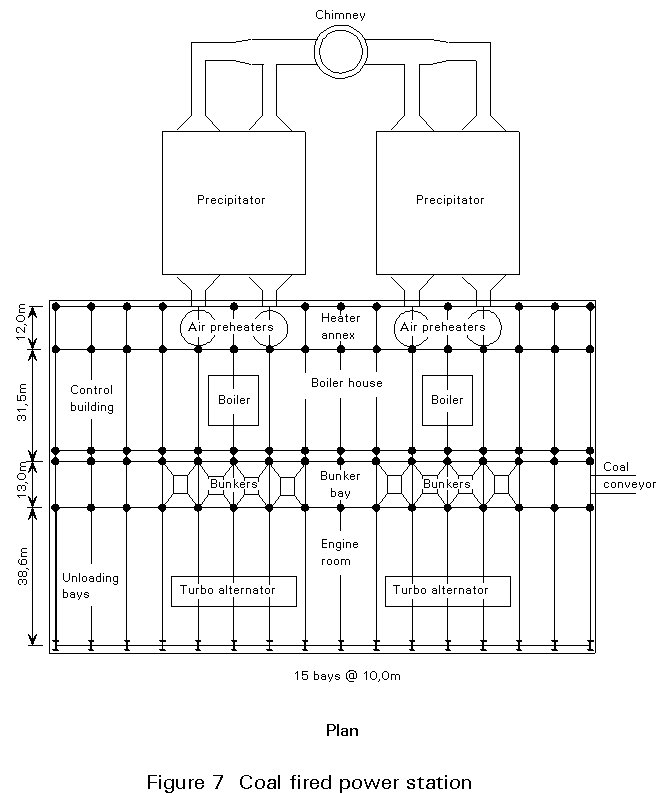
A typical medium-sized power station (Figures 7 and 8) consists of a 38,6m span turbine hall, flanking a 13m span bunker bay beside a 31,5m span boiler house and 12m wide air heater building. The height of the turbine hall is typically 30m, determined by the servicing requirements of the turbines and generators. The height of the bunker bay, which stores several hours fuel, and that of the boiler house are similar, determined by the height of the boiler and the size of the fuel mill below, and is typically 60m. The length of the building depends on the number of generators installed, each having its own boiler.
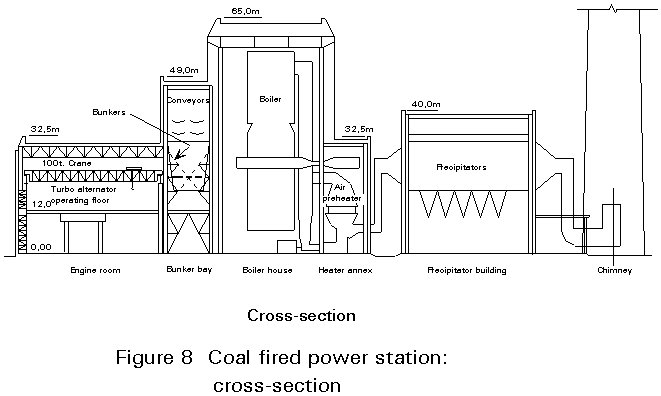
This type of power station is constructed almost entirely of structural steelwork and steel cladding. Steel construction is chosen because the completion of the boiler house is always on the critical path of the execution schedule. The execution of the boiler frame, designed to suit the boiler and from which the boiler is suspended, is central to the schedule. The stanchions of the boiler frame, often six in number, are typically compound H-section, carrying up to 1000 tonnes each, and the boiler is suspended from heavy plate girders spanning across the stanchions. The external steelwork to the boiler house is relatively light, being mainly supported by the boiler frame which also braces the building.
In the bunker bay, which is also a steel structure, are large feed bunkers of 600 tonnes capacity constructed of steel plate, supported at high level, to which fuel is supplied by conveyors. There is a fire and explosion hazard in the feed conveyors and the ductwork connecting the bunker to the fuel mill and the latter to the boiler. Sprinkler and carbon-dioxide fire protection is therefore required in this part of the plant, and fire protection is also applied to the steelwork.
In the turbine hall the generator sets are supported 10m above floor with condensers fitted below. Due to the weight of the generator sets the supporting structure, which is usually of steel but may be of concrete, is of heavy construction. To carry out maintenance of the generator sets a 100 tonne overhead crane travelling the length of the hall is provided, requiring heavy compound sidewall stanchions to support the runway beams. The roof structure is of light lattice girders except where additional strength is required to facilitate the installation of the crane.
Provision for extension of the turbine hall can be made, but extension of the boiler house depends on the choice of boiler, so that the ease of joining to existing steelwork has to be relied upon.
Maintenance of the generating plant is an important consideration in the design of a power station. Maintenance of the building is reasonably straightforward, since generation does not create aggressive conditions or waste. Corrosion is not a major problem, so that it is adequate to shot-blast and coat the steelwork.
The construction of power stations of this type displays the versatility of steel, its use varying from heavy steelwork for the support of plant to light roof steelwork and sheeting. Allied to this versatility is speed of execution on site, which off-site fabrication allows. It is therefore understandable that steel is used almost exclusively in this field of application.
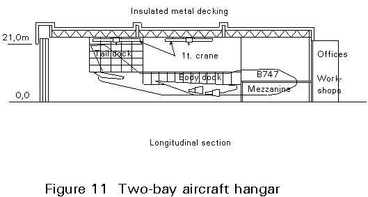
A typical hangar bay for the maintenance of Boeing 747 aircraft (Figures 9 - 11) is 76m wide and 97,5m long, and the hangar may consist of one, two or three bays. The maximum clear height is usually 23,5m to allow clearance over the 20m high tail fin of the aircraft, but only 17m is required over the body and main wings. The roof may therefore have two levels, the height in the tail area being 23,5m, the remaining area 17m. The two-level roof restricts the attitude of the aircraft to nose-first, whereas a full-height hangar allows either nose-first or tail-first attitude. At the rear of the hangar is the 2-3 storey workshop and administration block, 10m deep and the same width as the hangar. The roof slope is usually small to avoid excessive height, utilising either an insulated roof membrane on metal decking or insulated two-layer cladding. The roof structure is usually comprised of lattice trusses, girder or portal frames, but double-layer grid space frames have also been used.
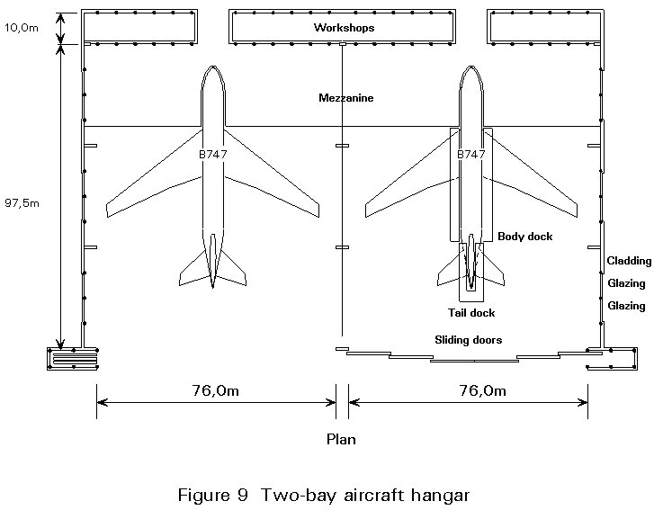
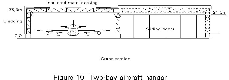
The main door is usually 21m high, and can be a sliding-folding or slab-sliding design. The full opening width required is 80m. If bunching space for the doors overlaps the door opening the bay width is increased correspondingly. Some hangar doors are only 14m high with a 7m high tail gate, or they may have a vertically folding 21m high centre section.
Whilst some smaller hangars have been constructed in prestressed concrete, virtually all are now constructed in structural steelwork with insulated steel cladding.
Hangars are specialised for maintenance of one type of aircraft or a mix of types. Access to an aircraft, because of its shape and size, is a problem which is best solved by specially designed docking tailored to suit the particular aircraft. This arrangement enables a large workforce to carry out maintenance. Typically the docking consists of main wing docks, a tail dock and body dock. They are moved into place after the aircraft has been placed in a fixed position. Since aircraft are jacked up 1,5m for landing gear overhaul, it is usually necessary for the docks to have vertical adjustment. The use of wheel pits can make jacking unnecessary, but these add considerably to cost as well as adding to specialisation.
Unless they can be moved out of the hangar, docks occupy a large amount of floor space. They obstruct the placing and maintenance of other types of aircraft when not in use. Consequently tail docks and body docks are sometimes suspended from the hangar roof. Since tail docks weigh 12-50 tonnes and body docks 50-100 tonnes, provision for them must be incorporated in the roof design.
Hangars are usually provided with light overhead cranes covering the full area. They are used to handle dismantled parts up to 1 tonne weight. Isolated engine hoists up to 10 tonne capacity may also be provided. Alternatively the overhead cranes may be of 10 tonne capacity. Conflict can arise between cranes and suspended docking. If a two-level roof is adopted, separate cranage is required in the tail bay.
Electric power, air and other services may be from roof-mounted motorised reels or in the floor. Heating is by embedded floor coils or high-power blowers suspended from the floor. Blowers are large units appropriate to the height of the hangar. Sprinklers may be installed, depending on the extent of the maintenance carried out and the safety procedures adopted regarding on-board fuel.
Except for roof maintenance, the maintenance requirements for a hangar are usually slight, since aggressive emissions are confined to drainage from the hangar floor where painting is carried out, or from cleaning or chemical process shops. Due to the large roof area and its height, and to the characteristically exposed environment of an airport, storm damage is always possible. Roof leaks can have very serious consequences, because of the high value of aircraft parts.
Developments in aircraft design and increased competition for contract maintenance make it necessary to allow for modifications to a hangar. The introduction of the 747 type and other wide-body aircraft compelled the extension of many of the hangers in use at that time. However, the intensive usage of a hangar and the strict fire and safety regulations applied when aircraft are inside makes modification difficult to carry out. Flexibility therefore needs to be allowed for at the design stage.
The superiority of structural steelwork for aircraft hangars is now well established. The speed of construction, suitability for large-span roofs, versatility for the mounting of various services and docks, and the adaptability for future development virtually exclude other structural materials.
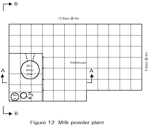
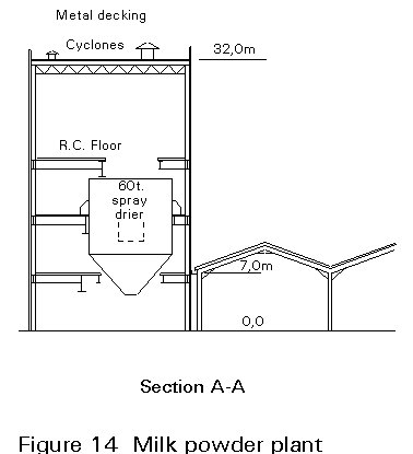
A typical milk powder plant (Figures 12 - 14) consists of a spray-drier tower 18m by 17m by 32m high with an external boiler house, a silo and packing plant annex 16m by 18m, and a storage warehouse for packaged powder 54m by 54m with 7m clear height for fork-lift transport and stacking.
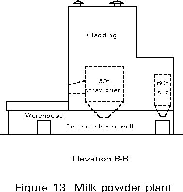
The tower and annex are framed in structural steelwork, with composite concrete floor and steel cladding. The warehouse typically has multi-bay short-span portal frames carrying pressed steel purlins and asbestos cement or single-skin metal cladding.
The spray drier is a 10m dia. stainless steel drum 14m high, supported at several floors. Milk and hot air are injected at the top, and the dry milk powder collects in the hopper bottom. From there it is conveyed to the silos of the packing plant. The floors are lightly loaded except for ancillary plant and the spray drier, which in operation weighs 60 tonnes.
There is an appreciable explosion risk from the finely divided milk powder. Strong explosion ducting with an exterior blow-out panel, intended to control the direction and result of an explosion, is incorporated in the drier, and provision for this facility is made in the tower steelwork.
The large amount of air injected in the process requires outlet cyclones to extract milk powder from the exhaust air. Even with regular maintenance, cyclones are never 100% efficient, so that some powder, which can accumulate quickly, escapes. Deposits of powder can cause problems with roof drainage, which therefore requires appropriate design. Milk powder contains lactic acid which is moderately aggressive particularly to flat roof coatings such as asphalt and felt. Consideration of the durability of the roof is therefore required.
Internally a biologically clean environment is required in order that the plant complies with process regulations. Easily cleanable surfaces are required internally. This requirement is best met by high quality internal sheeting. Avoidance of crevices which can cause lodgement of material affects the choice and detailing of any steelwork exposed internally.
Competition in milk powder production requires that first cost and running cost are carefully controlled. Since development of driers occurs, a change of drier may be necessary involving major alterations to the tower. The use of structural steelwork and cladding facilitates cost control in both construction and modification.
Some major industrial projects provide both the scale and the opportunity for adopting unusual structural forms which have particular advantages. A good example of an unusual structure form is the Renault Parts Distribution Centre in Swindon (Figures 15 - 17).
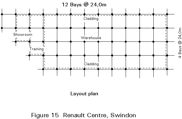
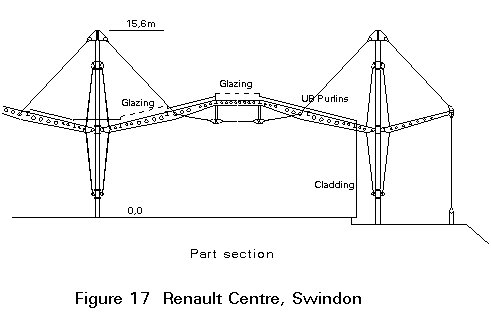
The requirement was for a single-storey building of 25.000sq.m containing a warehouse, training school, showroom and office, with provision for 50% expansion. To suit the storage arrangements for the warehouse a 24m x 24m bay was adopted, with 8m internal height, with 2,8% roof lighting and sidewall glazing in some areas. The main area is 4 bays wide and 9 bays long, with an additional 6 bays at one end.
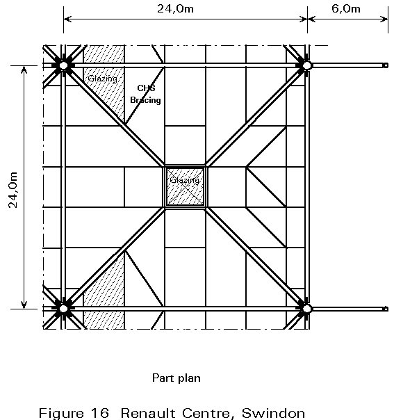
The structure consists of skeleton portal frames on both rectangular and diagonal axes. The main verticals are 16m high 457mm dia. circular hollow sections with rod stiffeners. The roof members are simple trusses formed from shaped I-beams cambered 1,4m stiffened on the underside with rod bracing and short tubular verticals. Continuity between the main verticals and the trusses is established by rod bracing connecting the heads of the main verticals to the quarter-points of the trusses. Whilst the internal verticals are balanced by trusses on each side, the perimeter verticals, which have transverse and diagonal trusses on one side only, are balanced by ground anchors bracing short beam members connected to the verticals at the same level as the trusses.
Macalloy bars are used for the rod stiffeners to the main verticals, and S355 steel is used for the main rod bracing. The rods are connected to the main verticals by purpose-made cast-iron eyes pinned to lugs welded to the 457mm dia. hollow sections, and to the trusses through sleeves set into the beam sections.
In each bay the trusses are cambered to a central 4m x 4m dome rooflight. The roofing consists of an insulated membrane on metal decking, which is carried on purlins between the trusses. Valleys formed by the cambered trusses are drained by downpipes incorporated in the main verticals. Both main vertical and bracing rods pass through the roof covering.
The overall appearance is unusual, resembling a large marquee due to the tent-like profiles of the cambered trusses and the main verticals and bracing rods protruding through the roof.