ESDEP WG 8
PLATES AND SHELLS
To introduce methods of global analysis, methods of determining cross-section distortion, and shear lag in box girder bridges.
None.
Lecture 8.5.1: Design of Box Girders
Global analysis may be made by the grillage, orthotropic plate, folded plate and finite element methods.
Distortion of the box may have to be controlled by diaphragms or cross frames. Simple or refined methods are available for the calculation of the forces in the diaphragms or cross frames.
In very wide flanges, shear lag effects have to be taken into account.
Although steel or steel-concrete composite box girders are usually more expensive per tonne than plate girders, because they require more fabrication time, they can lead to a more economic solution overall.
Box girders have several advantages over plate girders which make their use attractive:
The principal methods which are in use for the global analysis of box girder bridges, and their applicability to the various types of steel or steel-concrete composite bridges, are discussed below.
Most composite bridge decks fall into one of two groups.
In the first group beam theory can be used and the bridges can be idealised as a grillage or an orthotropic plate. They are the simplest to analyse. The box girders are assumed to be stiffened enough to stay undeformable. For uniform loading, elementary beam theory gives useful results, but distribution analysis by a grillage or an orthotropic plate method is needed for more complex loadings. Bridges in this first group include beam-and-slab configurations with multiple box girders.
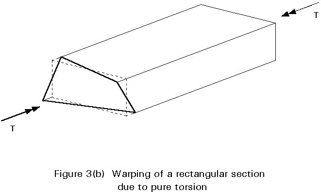
In the second group the effects of loading are best evaluated by dividing the load into bending, uniform torsional, warping torsional, distortional and local components. The Bredt and Leduc theory for thin-walled hollow sections gives the primary shear stresses due to torsion. Timoshenko and Vlassov have shown the validity of this hypothesis with the theory of undeformable girder sections : the Saint Venant torsional stiffness is much greater than the torsional warping stiffness. Bridges in this group include those in which the longitudinal members consist of a single closed box with a few internal webs.
However in both cases the torsional and bending stresses are accompanied by longitudinal torsional and distortional warping stresses. The distortional warping stresses are the consequence of the bending deformation of the section walls in the transverse plane coupled with the in-plane resistance of the walls of the box. Distortional stresses are usually several times larger than torsional warping stresses. They reach their maximum values at bearings, at cross-sections subjected to eccentric point loads, and at the location of the diaphragms which prevent the deformation of the girder section.
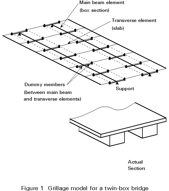
In the grillage analysis, the structure is represented by a plane grillage of discrete but interconnected beams. Almost any arrangement in plan is possible. Thus skew, curved, tapering or irregular decks can be analysed. The usual layout consists of sets of parallel beams in two directions. This type of layout is discussed below, assuming the plane of the grillage to be horizontal.
The method does not enable study of warping stresses and shear lag. Local effects in decks and slabs can only be studied with a grillage by the use of a dense network of beams.
In a simple form of grillage analysis, each beam is allotted a torsional stiffness and a flexural stiffness in the vertical plane. Vertical loads are applied only at the intersections of the beams. The matrix stiffness method of analysis is used by existing computer software to find the rotations about two horizontal axes and the vertical displacement at these nodes. Hence the bending and torsional moments and vertical shear forces in the beams at each intersection are found.
Care must be taken to select an appropriate idealisation for a continuous structure, and also to deduce the stress resultant in it from the results of the grillage analysis. The principal conclusions relevant to the design of composite structures are as follows:
For skew decks, the grillage cross beams should be parallel to the real cross members, if any. The stiffness and position of the real supports should be accurately modelled in the grillage. Real cross members can, with advantage, be skewed for skews up to about 20° , but for high skews they should be orthogonal. For decks without cross members, a skew grillage is preferred for skews up to about 30° because the preparation of input data for an orthogonal grillage is more complex. For highly skewed decks, the cross members, if any, and the grillage beams should be orthogonal, to avoid the high torsional moments inherent in skew layouts. Transverse reinforcement in the slab should be parallel to the transverse grillage beams.
The high torsional stiffness the box girder section may give rise to problems with highly skew bridges comprised of multiple boxes, each on separate bearings and the behaviour at the skew supports must be considered very carefully.
If the purpose is to model the local bending and shear effects in deck slabs, the concrete slab of a composite bridge should be represented by a dense network of members. The distance between two parallel members of the grillage should be 0,50 m. For a plane grid analysis, the torsional stiffness of such a concrete strip should not, for instance, be bt3/3 but should be reduced to only bt3/6, where b is the breadth of 0,50 m and t the thickness of the deck. This reduction is due to the fact that no Saint Venant shear stress flux goes around the perimeter of the strip's cross-section. Vertical local loads should be only applied at the intersections nodes of the beams.
To model the equivalent loads, approximately one half of the local load can be distributed over the eight nodes of the vicinity to get correct results, even near the loaded point.
For steel-concrete composite box girders, the areas of structural concrete are transformed to steel on a modular basis. The Young's modular ratio is used for flexure, and the ratio G steel / G concrete = 5 is used for torsion due to temporary traffic loads.
For a composite box girder bridge, with a concrete upper deck (Figure 3), the torsional stiffness K is, for example:
K =  =
= 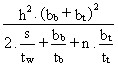
where n = G steel / G concrete = 5
Shear lag can usually be neglected in global analysis.
For regions where the concrete slab is in compression, the flexural stiffness is strictly that of the uncracked reinforced section. Even where the concrete has cracked under a traffic load, its stiffness remains. For these reasons, it is common to assume in global analysis that, for the computation of the beam rigidities, all concrete is uncracked and unreinforced.
Flexural rigidities of longitudinal members depend on the breadth of concrete slab that is assumed to be associated with each steel web. For the deck shown in Figure 4, arbitrary division of the deck midway between webs would result in the neutral axis of the beam web EH being higher than that of the beam with web FG. More rigorous analysis of concrete decks shows the neutral axes of all the longitudinal members to be almost at the same level across the width of the deck. Such analysis also suggests that the breadth of deck allocated to the web EH and FG should be more nearly equal, as shown by the lines A, B and C. This alternately suggests that the transverse position of the steel boxes under the slab can in this case be improved.
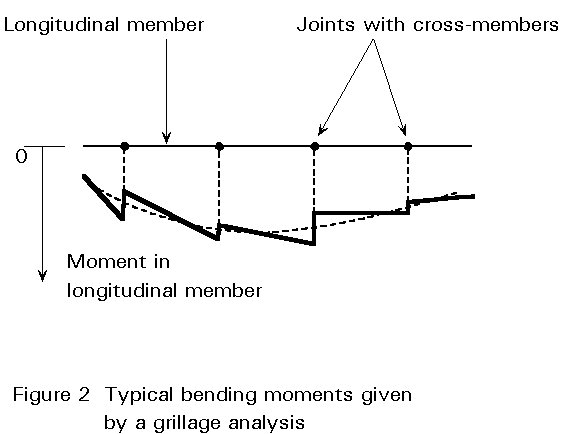
A typical output gives the external reactions at each support. These results should always be examined first. Computer software usually also gives values of the vertical shear, bending moments and torsional moment for each grillage member on both sides of each joint in the grillage. Care should be taken in deducing design values for the real members from these results. The values midway between two adjacent nodes are usually more representative of the real values.
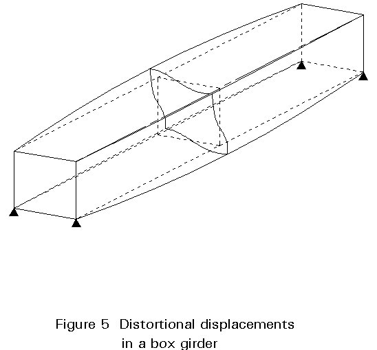
The bending and torsional moments, in general, show a discontinuity at each joint, Figure 5. For an orthogonal grillage, each change in bending moment is equal to the change in torsional moment at that joint in the member at right angles to the one considered. Similarly, the change in torsional moment equals the change in bending moment in the perpendicular member.
If the values midway between two adjacent nodes are not directly available, the design bending and torsional moments at each joint can be taken as the mean of the values on each side of the joint, for the member considered.
In orthotropic plate analysis, the deck structure is `smoothed' across its length and breadth and treated as a continuum.
The elastic properties of an orthotropic plate are defined by the two flexural rigidities Dx and Dy and a plate torsional rigidity H. The governing equation relating deflection w to load P acting normal to the plane of the plate is:
![]() = p(x, y)
= p(x, y)
Design charts for decks that can be idealised as orthotropic plates have been derived from series solutions. They give deflections and longitudinal and transverse moments due to a point load, and so provide a rapid method for distribution analysis. Their applicability is limited to simply supported decks of skew not exceeding 20° whose elastic properties can be represented solely by length, breadth, and the three quantities Dx, Dy and H.
In composite structures, they can be used for beam-and-slab decks with not less than five equally spaced longitudinal members of uniform diaphragms over the supports.
In practice, the method has often been superseded by grillage analysis.
The folded plate method is normally limited to assemblages of rectangular plates. It is not applicable to skew decks due to coupling between the harmonics. The orthotropic plates may extend over several spans but must be simply-supported at the extreme ends, with rigid diaphragms over the end supports. When folded plate diaphragms are used to represent the transverse frames, the advantages are that it can give a complete and accurate solution in much less computer time than is needed for the finite element method, and it can accept a wide variety of types of loading and both displacement and force boundary conditions.
If the deformations of the cross section of a single box girder bridge are assumed to be concentrated in the corners of the box girder, an analogy between this folded plate analysis and beam theory exists. The cross frames or the diaphragms transform the effect of eccentric loads into uniform of Saint Venant torsional shear stresses by resisting the resulting distortion. They become therefore the elastic supports for the box girder representing beam. This simplification offers an economic way of computing the internal forces in the cross frames of the box girder, as well as the distortion warping stresses.
To apply the same method to a double cellular box-girder bridge with one single internal web, the distortion must be divided into symmetric and asymmetric deformations. For boxes with more internal webs, it is possible to divide the deformations of the cross-section into eigenvalue functions of deformation.
The finite element method is used increasingly in civil engineering. It is the most versatile of the matrix stiffness methods of elastic analysis, and can, in principle, approach the solution of almost any problem of global analysis of a bridge deck. The finite element method is not only used for the study of statical problem, but for dynamic problems involving elasticity and/or plasticity. The finite element method allows the study of shear lag and the computation of effective flange breadths. It is also useful to study local effects in slabs.
Its disadvantage is its cost, especially because of the high level of expert time required for the idealisation of the structure. The expert's know-how is needed in selecting an appropriate pattern of elements, in determining the right limit conditions for boundary nodes along the supports or the symmetry axes, and in interpreting results. The choice of inappropriate elements can be misleading in regions of steep stress gradient, because the conditions of static equilibrium are not then necessarily satisfied. The selection of the discretisation density level, or of the material behaviour, may have serious repercussions on the accuracy of the results.
Other problems are that the method is generally not adapted to compute deformations and fabrication cambers.
Manual preparation of computer input and interpretation of output takes so much time that procedures for mesh generation and the plotting of trajectories of principal moment or stress are now incorporated into computer programs. Plotting procedures for the results may dangerously lead to underestimate of the maximum values of some effects, by computing non-representative average values.
Since a high level of expert judgement and experience are needed for use of the method, it should have little application in routine design work and is not therefore discussed further here.
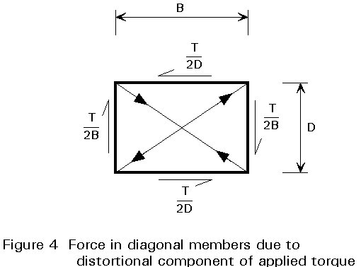
The distortional loading causes the cross-section of the box to change shape by bending of its walls in the transverse plane. The associated transverse bending and shear stresses are usually acceptable in the relatively thick walls of concrete boxes. However, in steel and steel-concrete composite boxes, diaphragms or cross frames may be required to control the distortion. Longitudinal distortional warping stresses also occur. In steel and steel-concrete composite beams, their relative size depends on the spacing of the cross frames.
The cross frames or the diaphragms transform the effect of eccentric loads into uniform of Saint Venant torsional shear stresses resisting the resulting distortion. In this way, the rigidity of the cross frames or diaphragms limits the deformations of the girder section in the transverse plane.
The distortion effects are combined with the local bending and shear in deck slabs in the vicinity of point loads. The calculation of local bending stresses in plates is simplified by the use of influence surfaces. Influence surfaces for simply supported plates tend to give high bending stresses in box girders because they do not consider the true boundary conditions of the plate panel.
The method often used in practice consists of isolating a segment of the box girder bridge with a length is equal to the distance between two adjacent diaphragms or cross-frames. One diaphragm or cross frame is located in the centre of this segment. All the external loads applied to the segment are assumed concentrated on the cross frame. The segment is also assumed to exchange uniform Saint Venant torsional shear stresses, as well as bending shear forces with the rest of the bridge at both ends of the segment. All these shear stresses are also concentrated on the cross-frame.
The diaphragm or cross-frame, is then calculated under the equilibrium set of actions. Their resulting dimensions are usually economic and acceptable.
The distortion forces due to the loads applied to the segment described above are resisted in fact by more than a single diaphragm or cross frame. Analysis as a beam on an elastic foundation is one way of computing the distribution of the distortion loads over the different diaphragms or cross-frames considered as elastic supports.
Figure 6 shows the distortion force which will be reduced in the refined method. For the simplicity of the example, the one box girder section is only loaded by two opposite forces applied to the top corners.
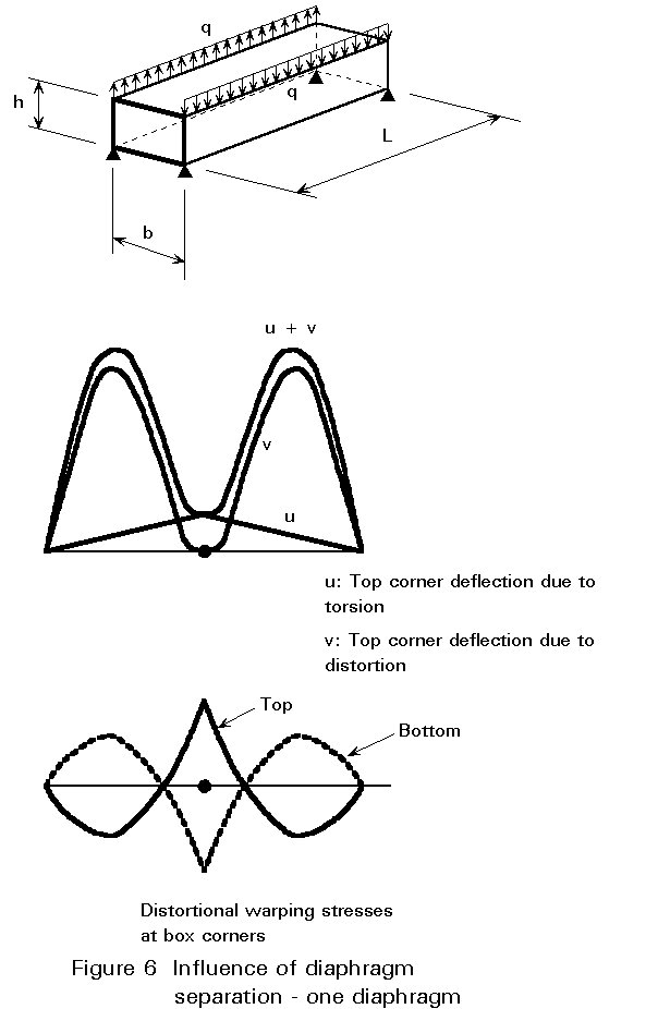
Figure 7 shows a parametric study of the influence of diaphragm separation for a simple box.
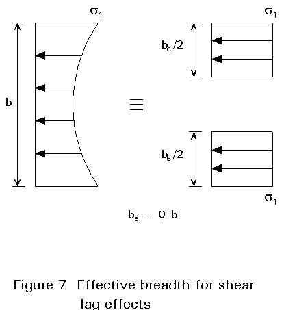
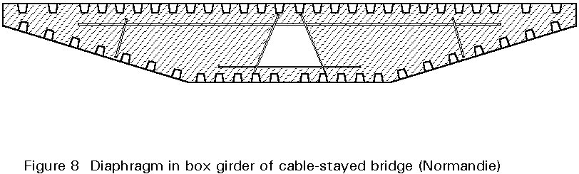
Figure 8 shows the distribution of the distortion forces in the different cross-frames of a four-span bridge in one of the two main spans of 80 m. The results were obtained from a folded plate analysis using diaphragms to represent the frames.
The local effects of reactions at bearings cause complex states of stress in the support diaphragms and stress concentrations in the adjacent webs. The cross frame is usually a diaphragm on piers to obtain the greatest rigidity to resist distortion. If the bearings on the piers are under the diaphragm, care must be taken to avoid dilation problems due to longitudinal eccentricity occurring at the bearings. Dilation is a particular problem with steel diaphragms which suggests that concrete or composite members could be used more often in this location, where extra weight is easily carried. However this consideration is not the only one to take into account in developing the concept of these elements. In addition they must resist corrosion during their life, and allow the regular inspection of the welded connections.
In very wide flanges, shear lag effects, which are neglected in the global analysis, have to be taken into account for the verification of stresses, especially for short spans.
Shear lag must be considered when verifying sections and calculating stresses, since it frequently causes the longitudinal stress at a flange/web intersection to exceed the mean stress in the flange by 20%.
In calculations based on the elementary theory of bending, an effective flange breadth less than the real breadth can be used. This effective flange breadth depends on the ratio of width to span.
For a simply supported beam, for example, the effective breadth of the portion between the webs is F e.b , where F e , the effective breadth ratio, is given in Table 1.
|
b/L |
Mid-span |
Quarter-span |
Support |
|||
|
a = 0 |
a = 1 |
a = 0 |
a = 1 |
a = 0 |
a = 1 |
|
|
0,00 0,05 0,10 0,20 0,30 0,40 0,50 0,75 1,00 |
1,00 0,98 0,95 0,81 0,66 0,50 0,38 0,22 0,16 |
1,00 0,97 0,89 0,67 0,47 0,35 0,28 0,17 0,12 |
1,00 0,98 0,93 0,77 0,61 0,46 0,36 0,20 0,15 |
1,00 0,96 0,86 0,62 0,44 0,32 0,25 0,16 0,11 |
1,00 0,84 0,70 0,52 0,40 0,32 0,27 0,17 0,12 |
1,00 0,77 0,60 0,38 0,28 0,22 0,18 0,12 0,09 |
Table 1: Effective breadth ratio F e for simply supported beams
where
b is the distance between webs.
L is the span of the beam
a
=F
e is the elastic effective breadth ratio.Several methods of global analysis are available:
Particular consideration is required for the choice of grillage, skew bridges, local effects in decks, torsional and flexural rigidities of grillage members, longitudinal grillage members, and the interpretation of the output.
a simple method.
a refined method.